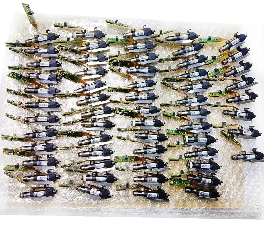
Used ASM SIPLACE D4 for PCBA assembly with four C&P12 heads, 66,000 CPH benchmark output and 144 feeder tracks.
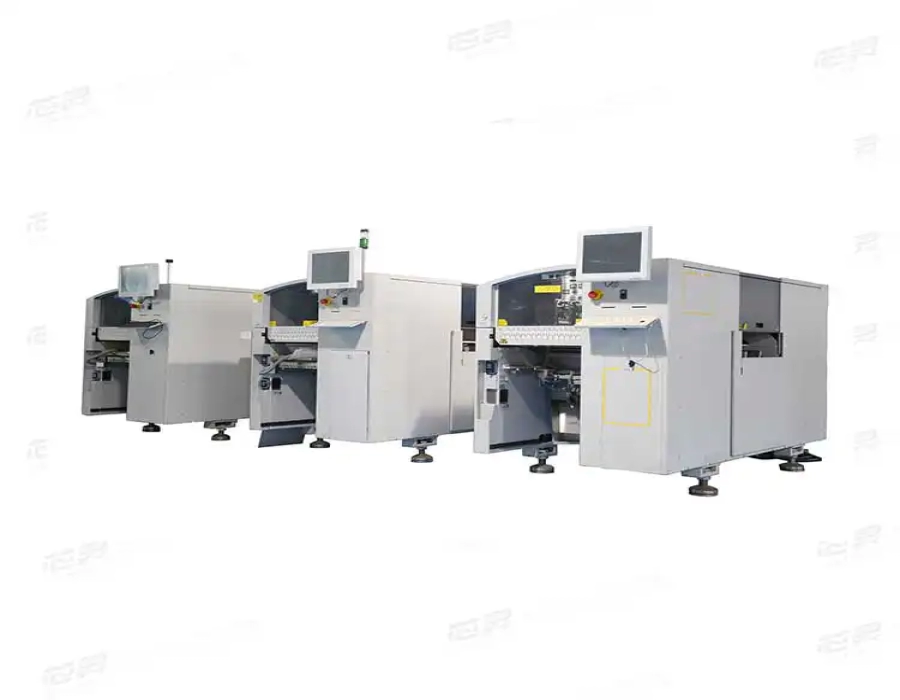
The ASM SIPLACE D4 pick and place machine is a four-gantry SMT placement platform designed for high-volume PCBA assembly involving large quantities of small and medium-sized surface-mount components. A typical high-output configuration uses four 12-nozzle Collect & Place heads to combine rapid component pickup, optical inspection and controlled placement within one machine.
For PCBA manufacturers, the value of the SIPLACE D4 is not based only on its maximum CPH rating. Its four-gantry architecture, stationary PCB placement principle, digital component vision, vacuum monitoring and placement-force control help maintain repeatable production across component-dense boards and long manufacturing runs.
GEEKVALUE supplies available used, inspected and refurbished SIPLACE D4 and D4i machines according to the actual machine label, placement-head condition, conveyor configuration, feeder package, software version and production application. View the complete ASM Siemens SIPLACE D Series to compare D1, D1i, D2, D2i, D3, D3i, D4 and D4i configurations.
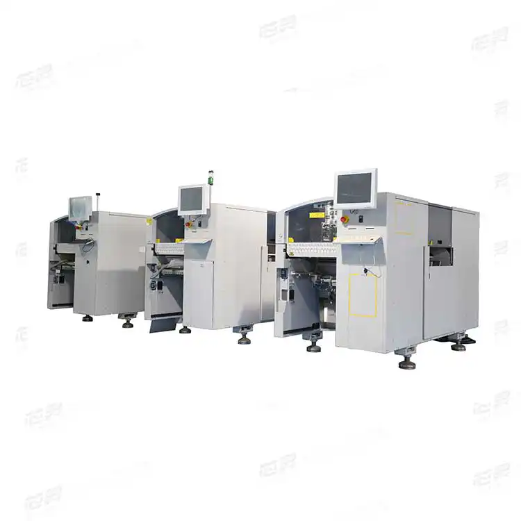
The SIPLACE D4 is primarily a high-speed component-placement machine. It is suitable for PCB assemblies containing large quantities of resistors, capacitors, small diodes, transistors, arrays, LEDs and compatible integrated-circuit packages.
The machine uses four independently controlled placement gantries. Each gantry is normally equipped with a 12-nozzle Collect & Place head, providing four placement heads and a total of 48 nozzle positions across the machine.
During production, the placement program distributes components and PCB coordinates across the four gantries. Each head collects several components from its assigned feeder area, verifies them through the vision system and places them onto the stationary PCB.
Four independently operating placement gantries
Four 12-nozzle Collect & Place heads
Up to 48 nozzle positions across the complete machine
57,000 CPH IPC placement performance
66,000 CPH SIPLACE benchmark performance
81,500 CPH theoretical maximum performance
Placement accuracy of approximately ±50 μm at 3 sigma
Up to 144 positions for 8 mm S feeder tracks
Single-conveyor and flexible dual-conveyor options
Configuration-dependent 01005 component capability
Suitable for high-volume PCBA and EMS production
| Specification | Typical SIPLACE D4/D4i High-Speed Configuration |
|---|---|
| Machine type | Four-gantry high-speed SMT pick and place machine |
| Number of gantries | 4 |
| Placement-head configuration | 4 × 12-nozzle Collect & Place heads |
| Total nozzle positions | 48 across four placement heads |
| IPC placement performance | Up to approximately 57,000 CPH |
| SIPLACE benchmark performance | Up to approximately 66,000 CPH |
| Theoretical maximum performance | Up to approximately 81,500 CPH |
| Component range | Approximately 01005 to 18.7 × 18.7 mm, depending on the installed package |
| Maximum component height | Approximately 6 mm with the C&P12 head |
| Placement accuracy | Approximately ±50 μm at 3 sigma and ±67 μm at 4 sigma |
| Angular accuracy | Approximately ±0.53° at 3 sigma and ±0.71° at 4 sigma |
| Feeder capacity | Up to 144 tracks using 3 × 8 mm S feeder modules |
| Maximum PCB format | Up to approximately 610 × 508 mm with the applicable conveyor options |
| PCB thickness | Approximately 0.3–4.5 mm; other thicknesses require confirmation |
| Maximum PCB weight | Approximately 3 kg |
| PCB conveyor | Single conveyor or flexible dual conveyor |
| Component supply | Tape feeders, stick magazines, bulk cases and application-specific feeder modules |
| Typical production role | High-volume placement of small and medium SMD components |
| Available machine condition | Used, inspected or refurbished, subject to actual availability |
Configuration notice: Used-equipment listings frequently combine SIPLACE D4 and D4i specifications. The exact model, smallest supported component, conveyor capacity, camera type, software version and installed options must be confirmed from the actual machine nameplate and powered-on inspection.
High-quality PCBA production requires more than fast mechanical movement. Component pickup, optical recognition, PCB positioning, placement force, feeder accuracy and conveyor stability must work together.
The SIPLACE D4 supports these requirements through a combination of vision and process-control functions.
Each collected component passes through the digital vision system before placement. The system checks the component position and rotation at the nozzle and calculates the correction required before the component is placed onto the PCB.
Depending on the camera configuration, different illumination levels can be used to recognize package shapes, leads, surfaces and component edges.
The component sensor checks whether a component is present at the nozzle before and after the pickup and placement operation. This helps identify missing pickups, failed releases and abnormal component handling.
The vacuum sensor checks whether the component has been picked up and released correctly. Vacuum instability may indicate a damaged nozzle, worn sleeve, blocked vacuum path, unsuitable component surface or incorrect feeder pickup position.
The force sensor monitors the programmed component set-down force. It can compensate for pickup-height differences and variations in the PCB surface during placement.
This is particularly important for small components, thin PCBs and assemblies where excessive placement force could disturb the solder paste deposit or damage the component.
The PCB camera recognizes programmed fiducials and calculates the actual board position before placement. The system can correct placement coordinates according to PCB offset and rotation.
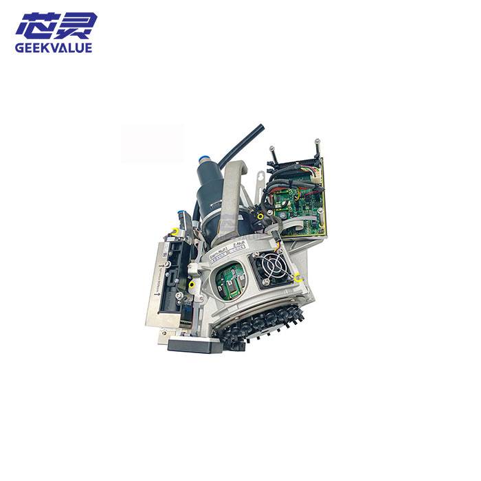
The C&P12 placement head contains twelve nozzle positions arranged around a rotating head assembly. Instead of returning to the feeder area after every individual component, the head collects several components during one operating sequence.
A typical placement cycle includes:
The head moves to its assigned feeder area.
Up to twelve components are collected by the nozzle positions.
The components pass through optical inspection.
Pickup offsets and component rotation are calculated.
The head moves to the stationary PCB.
Components are placed at their programmed coordinates.
Vacuum and component sensors verify the placement process.
This principle reduces repeated travel between the feeder area and PCB while maintaining component recognition before placement.
Multiple components can be collected during one head cycle
Pickup offsets can be corrected before placement
Component rotation can be checked and adjusted
Missing components can be detected
Placement force can be monitored
The PCB remains stationary during placement
Head travel can be reduced through feeder optimization
Four heads can share the complete placement workload
The four gantries provide the D4 with its high placement capacity, but the production program must distribute work efficiently across all four heads.
If one gantry is assigned significantly more components than the others, the remaining heads may complete their work early and wait for the busiest gantry. The maximum published machine speed will then not reflect the actual board cycle time.
Number of placements assigned to each gantry
Location of high-volume feeders
Distance between feeder pickup positions and PCB coordinates
Component package and nozzle requirements
Required component rotation
PCB dimensions and panel arrangement
Feeder indexing time
Nozzle-change frequency
Pickup retries and component rejection rate
Conveyor loading and unloading time
A realistic production-capacity assessment should use the actual BOM and placement program instead of dividing the component quantity by the theoretical 81,500 CPH value.
| Performance Value | D4/D4i Rating | Meaning |
|---|---|---|
| IPC performance | Up to 57,000 CPH | Measured according to standardized IPC test conditions for machine comparison. |
| SIPLACE benchmark | Up to 66,000 CPH | Measured according to defined SIPLACE machine-acceptance conditions. |
| Theoretical maximum | Up to 81,500 CPH | Calculated under highly favorable component, feeder and travel conditions. |
| Actual PCBA output | Application-dependent | Determined by the real PCB, component mix, program, conveyor cycle and machine condition. |
The theoretical rating should not be advertised as guaranteed production output. Real line performance must also include solder-paste printing, SPI inspection, flexible component placement, reflow and AOI cycle times.
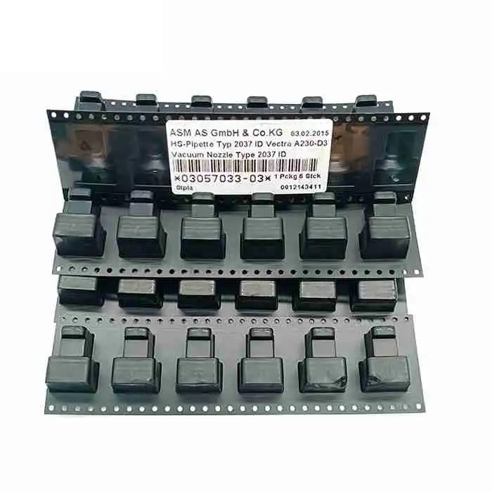
A standard C&P12 configuration is designed mainly for small and medium-sized surface-mount components.
Typical supported components include:
Chip resistors
Multilayer ceramic capacitors
Small diodes
SOT transistors
Resistor and capacitor arrays
Small-outline integrated circuits
Selected CSP and BGA packages
Small QFP and PLCC packages
LED components
Other compatible tape-fed SMD packages
The D4 is not normally selected as the only placement machine when a PCBA contains large connectors, tall components, heavy devices or irregular mechanical parts. These components are generally assigned to a flexible mounter equipped with a C&P6, Pick & Place, TwinHead or another suitable placement head.
Selected D4i configurations can process 01005 components, but the complete production capability depends on the installed hardware and software package.
A suitable 01005 setup may require:
Compatible C&P12 placement heads
High-resolution digital component cameras
Low-force placement sleeves
Type 905 or application-specific nozzles
Compatible high-precision S feeder modules
Suitable machine-station software
Compatible SIPLACE Pro programming software
Correct feeder and head calibration
Stable component-tape pocket quality
Accurate solder-paste printing
Controlled factory temperature and humidity
The machine model alone should not be used to promise stable 01005 production. A pickup and placement test using representative components is recommended before shipment.
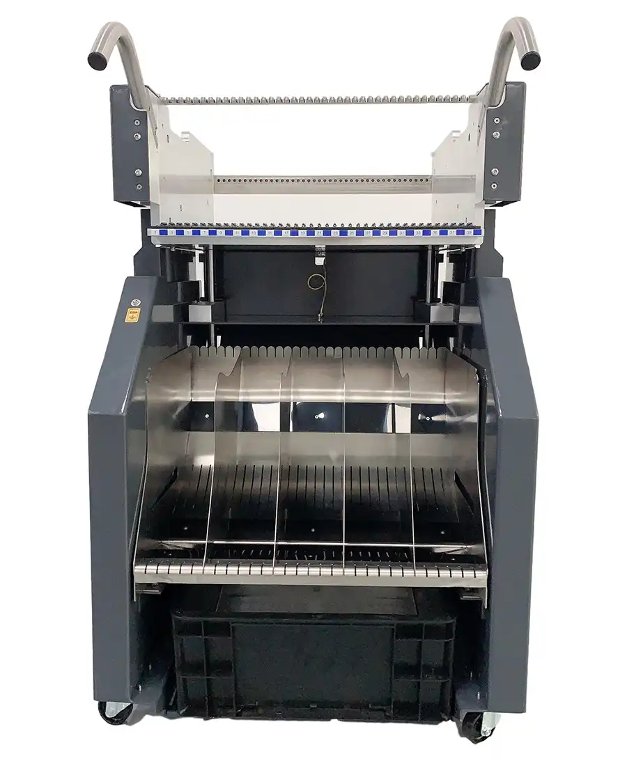
The SIPLACE D4 can provide up to 144 individual 8 mm tracks when configured with four component changeover tables and 3 × 8 mm S feeder modules.
This large feeder capacity is useful for PCBAs containing many component part numbers. It can also reduce the number of feeder changes required between related products.
Wider tape feeders occupy additional positions, so 144 tracks does not mean that 144 physical feeders of every width can be installed.
Number of component changeover tables
Number of 3 × 8 mm S feeder modules
Quantity of 12 mm, 16 mm and wider feeders
Feeder generation and part numbers
Feeder calibration condition
Pickup and indexing performance
Changeover-table communication condition
Table docking and locking condition
Reel holders and tape-waste containers
Spare feeder requirement
The phrase “144 tracks” describes tape-feeder capacity. It should not be described as tray-feeding capacity. Tray systems and tape feeders are different component-supply methods.
The SIPLACE D4 may be fitted with a single conveyor or a flexible dual conveyor. Maximum board dimensions depend on the installed long-board and wide-board options.
| Conveyor Configuration | Typical PCB Range |
|---|---|
| Standard single conveyor | Approximately 50 × 50 mm to 368 × 460 mm |
| Single conveyor with wide-board option | Up to approximately 368 × 508 mm |
| Single conveyor with long-board option | Up to approximately 610 × 460 mm |
| Single conveyor with long- and wide-board options | Up to approximately 610 × 508 mm |
| Standard flexible dual conveyor | Approximately 50 × 50 mm to 368 × 216 mm per lane |
| Dual conveyor with wide-board option | Up to approximately 368 × 242 mm per lane |
| Dual conveyor in wider single-lane mode | Up to approximately 368 × 380 mm |
| Long-board dual-conveyor configuration | Up to approximately 610 mm in length, depending on the installed option |
The flexible dual conveyor may operate synchronously or asynchronously. In asynchronous operation, one PCB can enter or wait while another board is being processed, reducing non-productive conveyor time.
Minimum and maximum PCB dimensions
PCB thickness
Maximum panel weight
Single-lane or dual-lane requirement
Same or different product on each lane
PCB transport direction
Fixed conveyor-rail position
Required line height
PCB edge clearance
Long-board or wide-board requirement
PCB support and warpage requirement
SMEMA or Siemens interface requirement
The D4 is normally responsible for the high-speed placement section of the SMT line. A complete PCBA line may include:
PCB loader
Solder paste printer
3D solder paste inspection system
ASM SIPLACE D4 high-speed placement machine
Flexible placement machine for large or odd-shaped components
Reflow oven
Automatic optical inspection system
PCB unloader
The D4 places most small tape-fed components, while the flexible mounter completes large ICs, connectors, tray-fed components and irregular devices.
SIPLACE D1 or D1i
SIPLACE D2 or D2i
SIPLACE F5 HM
Other compatible SIPLACE flexible placement platforms
The total line output is determined by the slowest process. A D4 cannot increase complete PCBA output when the printer, flexible mounter, reflow oven or inspection system remains the primary bottleneck.
Telecommunications equipment
Industrial control boards
Automotive electronic modules
Computer and server electronics
Network equipment
Consumer electronic products
LED driver and control boards
Power-supply PCB assemblies
Medical electronic products
High-volume EMS production
The correct equipment combination should be selected according to component count, package range, PCB dimensions, target cycle time and the quantity of components requiring flexible placement.
Used machines may be advertised as ASM D4, Siemens D4, Siemens Dematic D4 or SIPLACE D4i. These names should not be treated automatically as the same configuration.
Before quotation, verify:
Complete model printed on the machine nameplate
D4 or D4i designation
Machine serial number
Manufacturing year
Station-software version
Installed component-camera type
01005 package availability
Conveyor type and installed extensions
Number of component changeover tables
Placement-head labels and condition
The D4i documentation should not be applied automatically to an original D4 unless the relevant hardware and software are present on the actual machine.
A used D4 should be evaluated under powered-on operating conditions. Exterior appearance alone cannot confirm placement accuracy, head condition or production stability.
Complete model and serial number
Manufacturing year
Total operating hours
Total placement counter
Original and current configuration
Station-software version
Available machine backup files
Movement of all four gantries
X-axis and Y-axis noise
Vibration during acceleration
Machine homing and reference operation
Motor and encoder condition
Axis-drive alarm history
Cable-chain and trailing-cable condition
Gantry calibration and alignment
Condition of all four C&P12 heads
Head serial numbers and placement counters
Nozzle-sleeve wear
Rotary-star movement
Z-axis movement
Vacuum pressure and leakage
Component-sensor operation
Force-sensor operation
Nozzle-changer operation
Pickup and placement repeatability
Component camera on every gantry
High-resolution camera availability
PCB-camera image quality
Illumination-level operation
Component recognition
Fiducial recognition
Pickup-position correction
Camera calibration condition
Single or flexible dual conveyor
Automatic width adjustment
Synchronous and asynchronous modes
Conveyor belts and pulleys
PCB entrance and exit sensors
Board clamping and support
Long-board and wide-board options
Communication with surrounding equipment
Number of component tables
Number and type of included feeders
Feeder pickup and indexing performance
Table communication units
Docking and locking mechanisms
Reel holders and tape cutters
Waste-container condition
Feeder calibration records
A complete inspection video should show machine startup, homing, all four gantries, all four heads, feeder pickup, component recognition, nozzle changing, PCB transport and an actual placement program.
Required D4 or D4i model
Preferred manufacturing year
Required machine condition
Target PCBA production output
Smallest component package
Largest component assigned to the D4
Need for 01005 production
PCB dimensions and thickness
Single- or dual-conveyor requirement
Required feeder quantities
Required feeder tape widths
Existing SIPLACE machines and feeders
Factory voltage and frequency
Compressed-air availability
Destination country
Required delivery schedule
For cycle-time evaluation, provide the PCB BOM, placement file, panel dimensions, component list and target hourly output.
The D4 combines high-speed placement with controlled component recognition and placement accuracy. Its primary role is high-volume placement of small and medium SMD components.
A typical high-output D4/D4i configuration has four gantries and four 12-nozzle Collect & Place heads.
Published D4i values include approximately 57,000 CPH under IPC conditions, 66,000 CPH under SIPLACE benchmark conditions and 81,500 CPH as a theoretical maximum.
The published placement accuracy is approximately ±50 μm at 3 sigma and ±67 μm at 4 sigma. Actual results depend on machine calibration, head condition, feeders, nozzles, components and PCB quality.
Selected D4i configurations can process 01005 components when equipped with the correct cameras, sleeves, nozzles, feeders and software package. The capability should be tested on the actual machine.
The machine can provide up to 144 individual 8 mm tracks using four changeover tables and 3 × 8 mm S feeder modules. Wider feeders reduce the total installed quantity.
No. The 144-track specification refers to 8 mm tape-feeder positions. Tray feeding requires a separate tray or special component-supply system.
The maximum published PCB format is approximately 610 × 508 mm with the necessary long- and wide-board options. Standard conveyor configurations support smaller board formats.
Yes. Machines may be fitted with a flexible dual conveyor supporting synchronous or asynchronous production. The installed conveyor must be verified on the actual machine.
The standard C&P12 head is intended mainly for components up to approximately 18.7 × 18.7 mm and 6 mm in height. Larger connectors are normally placed by a flexible mounter.
Not automatically. Feeders, changeover tables, nozzles, computers and spare parts may be included or quoted separately. Every included item should be listed clearly.
Test all four gantries, all four placement heads, cameras, sensors, vacuum system, nozzle changers, conveyor, feeder tables, feeders, station computers and required software functions.
Send your PCB dimensions, component range, target output, feeder requirement, conveyor configuration and destination country. GEEKVALUE will check available ASM SIPLACE D4 and D4i machines and confirm the model, serial number, manufacturing year, head condition, conveyor, software, included accessories, inspection scope and delivery arrangement.
View the complete ASM Siemens SIPLACE D Series machine range, or review the ASM SIPLACE D4 technical overview for additional machine-selection and configuration information.
If you are not sure whether this product matches your machine, send us the model, label photo or old part picture for checking.