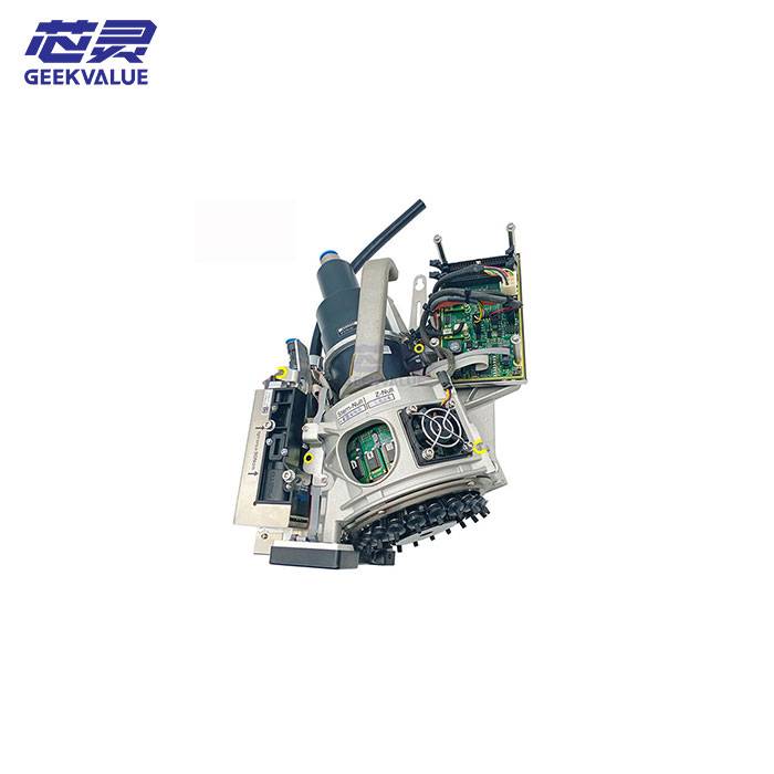
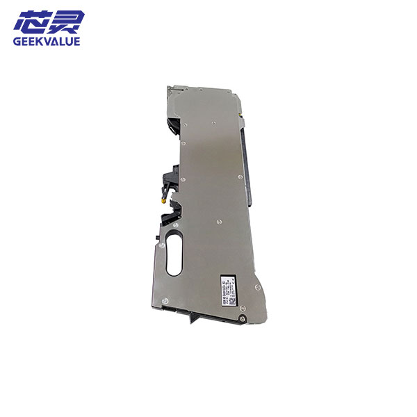
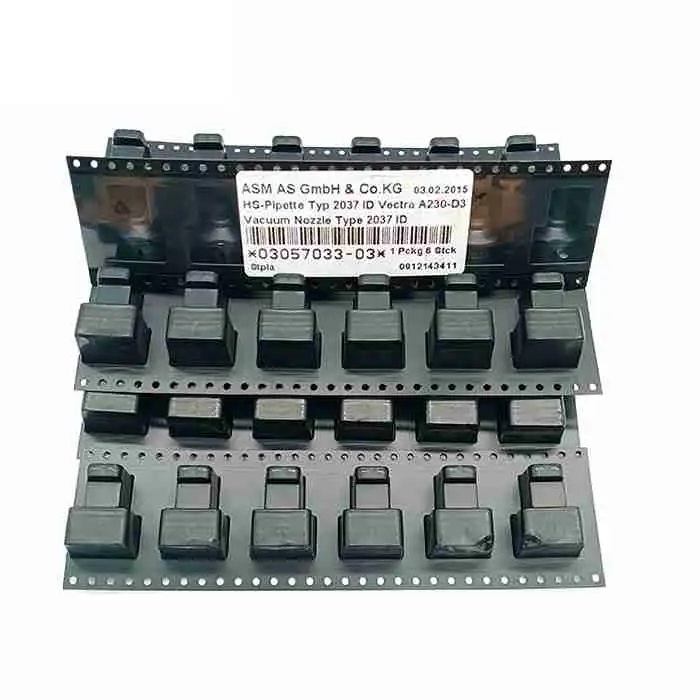
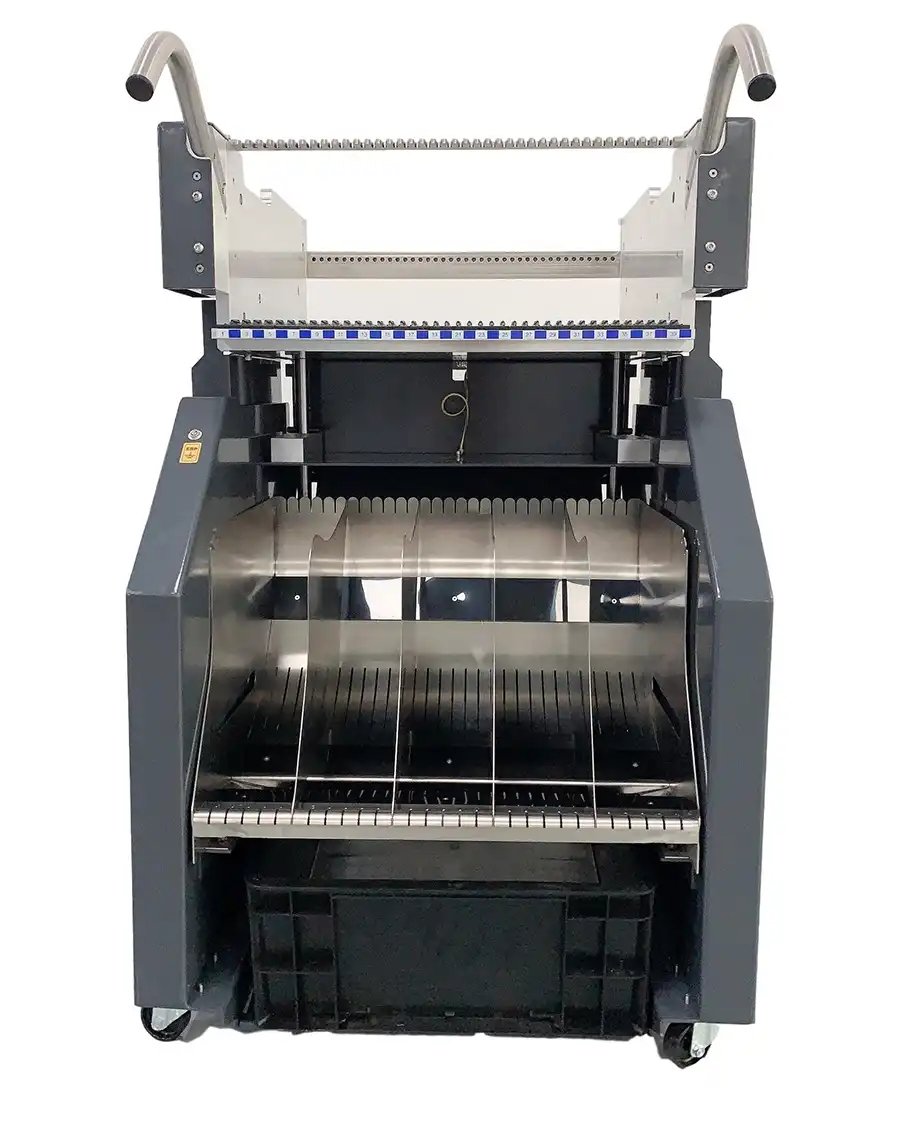
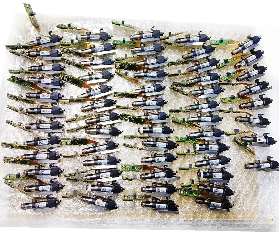
The SIPLACE D4i is a four-gantry SMT placement machine built around four 12-nozzle Collect & Place heads. This fixed head arrangement is intended for fast placement of standard SMDs and IC packages, with all four gantries contributing to the machine’s rat
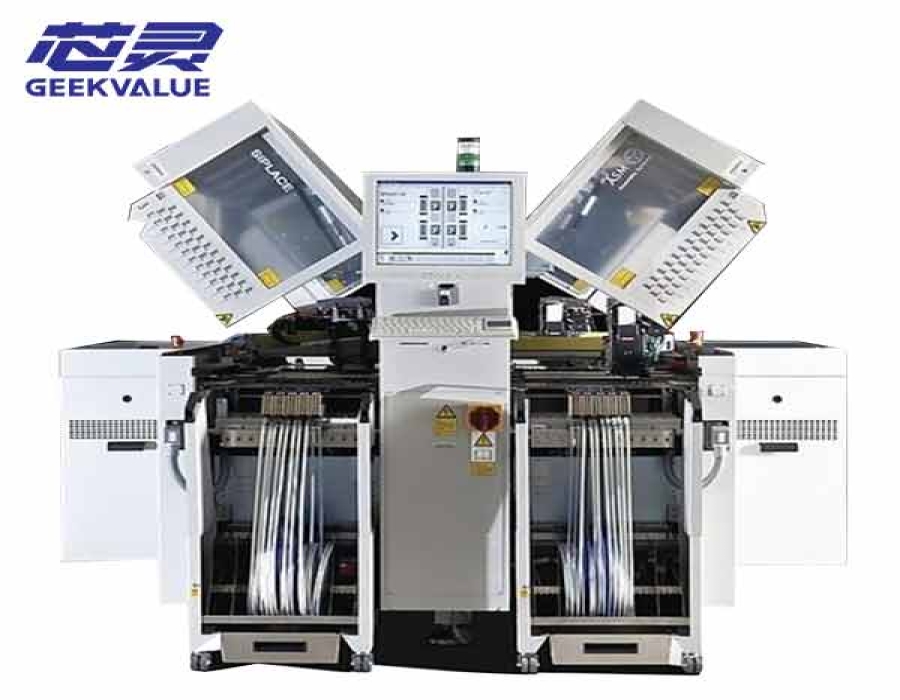
The SIPLACE D4i is a four-gantry SMT placement machine built around four 12-nozzle Collect & Place heads. This fixed head arrangement is intended for fast placement of standard SMDs and IC packages, with all four gantries contributing to the machine’s rated output.
Original SIPLACE specifications list an IPC 9850 placement rate of 57,000 components per hour and a SIPLACE benchmark value of 66,000 components per hour. Camera type, 01005 equipment, conveyor configuration, feeders and nozzle options can vary, so the available machine should be checked against the required production process before quotation.
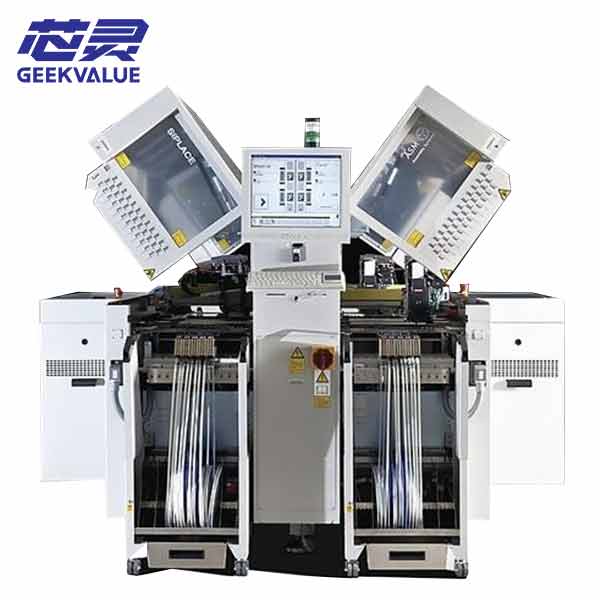
Each of the D4i’s four gantries carries one 12-nozzle Collect & Place head. During a placement cycle, the head collects multiple components from the feeder area, optically centers and rotates them while moving toward the board, and then places them at the programmed positions.
This architecture gives the D4i a clear production role: it is primarily a high-speed machine for boards containing a substantial number of chips, standard packages and compatible IC components. It is not a general odd-shaped-component platform, since the documented configuration does not include the large-component TwinHead or Pick & Place heads found on some other SIPLACE models.
| Machine Structure | Four placement gantries |
|---|---|
| Placement Heads | 4 × 12-nozzle Collect & Place heads |
| IPC 9850 Rating | 57,000 components per hour |
| SIPLACE Benchmark | 66,000 components per hour |
| Theoretical Maximum | 81,500 components per hour |
| Reference Placement Accuracy | ±50 µm at 3σ |
| Maximum Component Height | 6 mm |
| Maximum Component Weight | 2 g |
The theoretical figure represents operation under the most favorable calculated conditions. It should not be used as the expected output of an actual production program. Board layout, component mix, feeder positions, rotations, transport time and equipment condition all influence achievable throughput.
The D4i specification describes two camera configurations for its 12-nozzle head. Camera type 28 covers standard component placement, while camera type 30 extends the minimum component range when the dedicated 01005 package is installed.
| Head and Camera Configuration | Minimum Component Size | Maximum Component Size | Reference Component Range |
|---|---|---|---|
| 12-Nozzle Head with Camera Type 28 | 1.0 × 0.5 mm | 18.7 × 18.7 mm | 0402 components through compatible IC, BGA, µBGA, QFP and flip-chip packages |
| 12-Nozzle Head with Camera Type 30 | 0.4 × 0.2 mm | 18.7 × 18.7 mm | 01005 with the required package, plus compatible IC and advanced packages |
| Maximum Component Height | 6 mm |
|---|---|
| Maximum Component Weight | 2 g |
| Programmable Placement Force | 2.4 N to 5.0 N |
| X/Y Accuracy | ±50 µm at 3σ or ±67 µm at 4σ |
| Angular Accuracy | ±0.53° at 3σ or ±0.71° at 4σ |
01005 capability should not be assumed from the D4i model name alone. The available machine must have the appropriate camera, 01005 package, compatible feeder modules, nozzles and supporting software.
The standard placement-head functions include a digital camera, vacuum sensing, force measurement and PCB warpage checking. The camera measures the position of each component on the nozzle so that pickup offsets can be corrected before placement.
Vacuum sensing checks whether the component was picked and released correctly. Force measurement monitors the programmed placement force and helps compensate for pickup-height differences and uneven board surfaces.
| Function or Option | Purpose |
|---|---|
| Digital Head Camera | Measures component position and supports correction before placement |
| Vacuum Sensor | Checks component pickup and release |
| Force Measurement | Monitors placement force and compensates for height differences |
| PCB Warpage Check | Helps maintain controlled placement on uneven boards |
| High-Resolution Camera | Optional equipment associated with the extended component range |
| Nozzle Changers | Up to eight may be installed as optional equipment |
The SIPLACE D4i was available with a single conveyor or a flexible dual conveyor. In dual-track operation, two boards can be handled synchronously as one common panel or asynchronously, allowing one track to transport a board while the other is being processed.
PCB dimensions depend on the installed conveyor and the presence of wide-board or long-board equipment. The maximum 610 × 508 mm format therefore does not apply to every D4i configuration.
| Conveyor Configuration | Reference PCB Range | Required Setup |
|---|---|---|
| Single Conveyor | 50 × 50 mm to 368 × 460 mm | Standard configuration |
| Single Conveyor, Wide Board | 50 × 50 mm to 368 × 508 mm | Wide-board configuration |
| Single Conveyor, Long and Wide Board | 50 × 110 mm to 610 × 508 mm | Long-board option and wide-board configuration |
| Flexible Dual Conveyor | 50 × 50 mm to 368 × 216 mm per reference track format | Standard dual-conveyor configuration |
| Flexible Dual Conveyor, Long and Wide Board | 50 × 120 mm to 610 × 242 mm | Long-board option and wide-board configuration |
| Dual Conveyor in Single-Conveyor Mode | 50 × 50 mm to 368 × 380 mm | Dual conveyor operated as one transport path |
| PCB Thickness | 0.3 to 4.5 mm as standard |
|---|---|
| Maximum PCB Weight | 3 kg |
| Component-Free Handling Edge | 3 mm |
| PCB Changeover Time | Less than 2.5 seconds under the specified conditions |
| Production-Line Interface | SMEMA or Siemens interface, depending on configuration |
The D4i uses movable component changeover tables that can be prepared at the machine or in a separate setup area. Preparing the next product setup offline reduces the amount of production time required to replace a feeder configuration.
The original platform supports four component changeover tables. Each table provides 12 feeder-module locations, with the final number of 8 mm tape lanes depending on the feeder modules installed.
| Component Changeover Tables | Four |
|---|---|
| Module Locations per Table | 12 locations, each 30 mm wide |
| Reference Table Changeover Time | Less than one minute |
| Supported Feeder Types | Tape feeders, bulk-case feeders, stick magazines and compatible application-specific modules |
| Optional Setup Verification | Component barcode reader and Setup Center functions |
Feeder capacity is not the same as the number of feeders included with a used machine. Changeover tables, tape feeders, nozzles and alternative feeding modules should be listed individually in the quotation.
| Machine Length | Approximately 1,540 to 2,380 mm, depending on extension kits |
|---|---|
| Width with Changeover Tables | Approximately 2,511 mm |
| Basic Machine Weight | Approximately 2,984 kg |
| Weight with Four Changeover Tables | Approximately 3,280 kg |
| Fully Configured Reference Weight | Approximately 3,392 kg |
| Nominal Apparent Power | 3.3 kVA |
| Compressed Air Operating Pressure | Approximately 5.1 bar |
| Recommended Room Temperature | 15°C to 35°C |
Supply voltage, machine height, transport height and compressed-air consumption differ by regional version and installed options. These facility requirements should be checked against the identification and configuration of the machine offered.
| Item | Reason for Confirmation |
|---|---|
| Camera Type | Determines the minimum component range and whether the extended vision configuration is installed. |
| 01005 Package | 01005 placement requires dedicated hardware, feeders, nozzles and software. |
| Conveyor Configuration | Defines the supported PCB dimensions, track mode and production-line connection. |
| Wide-Board and Long-Board Options | The maximum board formats are only available with the corresponding equipment. |
| Feeder Tables and Feeders | They may be included with the main machine or supplied separately. |
| Nozzles and Nozzle Changers | The installed nozzle equipment must match the intended component range. |
| Software and Interface Version | Should be checked for existing line integration, programming and traceability requirements. |
| Machine Condition and Delivery Scope | Current photos, included accessories and equipment condition should correspond with the final quotation. |
GEEKVALUE can assist with sourcing SIPLACE D4i placement machines according to current availability. Although the four-gantry head architecture is defined by the model, available equipment may differ in camera configuration, conveyor type, feeders, nozzle equipment, software and machine condition.
Send us your PCB dimensions, minimum component size, required output, feeder requirements and destination country. We will confirm the available machine configuration, current photos, included equipment, price and estimated delivery time before quotation.
No. The D4i requires the applicable high-resolution camera configuration, dedicated 01005 package, suitable feeder modules, nozzles and software. These items must be verified on the available machine.
No. It is the theoretical maximum stated for favorable calculated conditions. The original specification lists 57,000 cph under IPC 9850 conditions and a 66,000 cph SIPLACE benchmark value. Actual board output depends on the production program and operating conditions.
The documented four-head configuration is limited to components up to 18.7 × 18.7 mm, 6 mm high and 2 g. Production requiring large, tall or heavy odd-shaped components normally needs a different placement-head platform.
Not automatically. The machine supports component changeover tables and several feeder-module types, but the actual feeder quantity and included accessories must be confirmed in the quotation.
If you are not sure whether this product matches your machine, send us the model, label photo or old part picture for checking.