The used ASM SIPLACE X3 S SMT machine is a three-gantry placement system suitable for replacing an existing X3 S, expanding an established SIPLACE X-Series S line or adding flexible placement capacity without changing the complete production platform. Mac

The used ASM SIPLACE X3 S SMT machine is a three-gantry placement system suitable for replacing an existing X3 S, expanding an established SIPLACE X-Series S line or adding flexible placement capacity without changing the complete production platform. Machine suitability depends on the installed placement heads, conveyor, feeder package, software generation and current mechanical condition.
A later high-speed SIPLACE X3 S configuration provides published benchmark performance of up to 112,500 components per hour and IPC performance of up to 97,050 components per hour. Earlier machines may carry different published ratings, including 127,875 CPH theoretical, 94,500 CPH benchmark and 78,100 CPH IPC performance.
This page focuses on used-machine selection, configuration verification, inspection and production-line matching. For a complete technical introduction, review the ASM SIPLACE X3 S placement machine specifications. You can also compare the complete ASM SIPLACE X S / XS Series.
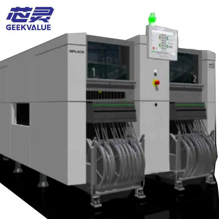
The SIPLACE X3 S is the three-gantry model within the X-Series S placement platform. Each gantry carries one placement head, giving the machine three independently controlled head positions.
The X3 S model designation does not automatically identify the exact head combination. One machine may be configured primarily for high-speed small-component placement, while another X3 S may use flexible or precision heads for larger ICs, trays, connectors and special components.
Three independently controlled placement gantries
Three installed placement-head positions
Later benchmark performance up to approximately 112,500 CPH
Later IPC performance up to approximately 97,050 CPH
Earlier theoretical rating up to approximately 127,875 CPH
CP20, CPP and TWIN placement-head options
Earlier SpeedStar, MultiStar and TwinHead terminology
Up to 160 positions for standard 8 mm SIPLACE X feeders
Single-conveyor and flexible dual-conveyor options
Support for high-speed chips, medium IC packages and selected special components
Suitable for direct replacement, production expansion and line rebalancing
| Specification | Used SIPLACE X3 S Reference |
|---|---|
| Machine platform | ASM SIPLACE X-Series S |
| Machine model | SIPLACE X3 S, commonly written X3S |
| Machine type | Three-gantry high-speed and flexible SMT placement machine |
| Number of gantries | 3 |
| Placement-head positions | 3 |
| Later placement heads | CP20, CPP and TWIN |
| Earlier placement-head names | SpeedStar, MultiStar and TwinHead |
| Later benchmark speed | Up to approximately 112,500 CPH |
| Later IPC speed | Up to approximately 97,050 CPH |
| Earlier theoretical speed | Up to approximately 127,875 CPH |
| Earlier benchmark speed | Up to approximately 94,500 CPH |
| Earlier IPC speed | Up to approximately 78,100 CPH |
| Platform component spectrum | Approximately 0201 metric to 200 × 110 × 25 mm, depending on the three installed heads |
| Best platform accuracy | Up to approximately 22 μm at 3 sigma with the relevant TWIN configuration |
| Feeder capacity | Up to 160 positions for standard 8 mm SIPLACE X feeders |
| Minimum PCB size | Approximately 50 × 50 mm |
| Maximum later platform PCB format | Up to approximately 850 × 685 mm with the applicable conveyor options |
| Earlier standard single-conveyor format | Approximately 450 × 560 mm |
| Earlier long-board format | Up to approximately 850 × 560 mm with the Long Board Option |
| Conveyor options | Single conveyor or flexible dual conveyor |
| Machine dimensions | Approximately 1.9 × 2.6 × 1.6 m on later platform data |
| Typical supply condition | Used, inspected or refurbished, subject to individual machine availability |
Important: The values above describe different X3 S documentation generations and platform capabilities. A used machine should only be quoted according to its verified model, manufacturing year, installed heads, conveyor, software and current condition.
The SIPLACE X-Series S platform includes several models with different gantry counts:
| Machine Model | Placement Gantries | Later Benchmark Performance | Typical Positioning |
|---|---|---|---|
| SIPLACE X2 S | 2 | Up to approximately 75,000 CPH | Flexible two-head production |
| SIPLACE X3 S | 3 | Up to approximately 112,500 CPH | Balanced high-output and flexible production |
| SIPLACE X4 S | 4 | Up to approximately 150,000 CPH | Maximum standard X S platform output |
| SIPLACE X4i S | 4 | Up to approximately 172,000 CPH | Highest-output X-Series S configuration |
An X3 S does not become an X2 S or X4 S through a simple software setting. The model and gantry count should be verified using the original machine nameplate and complete interior photographs.
A used X3 S is frequently selected to replace an installed machine without redesigning the complete SMT line. A direct replacement may preserve existing programs, feeder investments, operator training, maintenance knowledge and line layout.
An existing X3 S has suffered major gantry or control-system damage
Repair cost is approaching the cost of a complete replacement machine
The production line must return to operation quickly
The factory already owns compatible X feeders and component trolleys
Existing product programs were developed for the X-Series S platform
Operators and maintenance technicians are familiar with X3 S equipment
The surrounding printer, conveyors and reflow oven are already configured for the machine
A newer platform would require software, feeder and training changes
A replacement machine should not be selected only because the front label says X3 S. Head configuration, conveyor width, transport direction, software generation, line interface and voltage must also be matched.
A used X3 S can also be added to increase placement capacity in an existing line. The machine may be used as the main high-speed mounter, a mixed-component placement module or a flexible machine positioned after a higher-output chip placer.
An X3 S equipped with three CP20 or equivalent high-speed heads can increase placement capacity for boards containing large quantities of resistors, capacitors, diodes and other small tape-fed components.
This configuration may be suitable when:
The existing placement section is the line bottleneck
The PCB has a high number of small components
The factory has enough compatible feeders
Upstream printing and downstream reflow capacity can support the additional output
Production floor space is available for another X-Series S module
An X3 S equipped with CPP or earlier MultiStar heads can process small components together with medium-sized IC packages. This may reduce the workload assigned to an existing flexible mounter.
An X3 S equipped with a TWIN or earlier TwinHead configuration can be used for larger ICs, trays, connectors and selected special components.
An X3 S can be added to a line containing an X4 S when the high-speed machine is completing its work before the flexible component stage. Components can be redistributed according to head capability, feeder location and required cycle time.
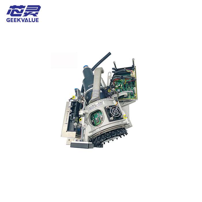
The three installed heads are the most important configuration detail on a used X3 S. Machines carrying the same X3 S model name can have substantially different output and component capability.
The CP20 and earlier SpeedStar production role is high-speed placement of small standard components. A later CP20 head supports components from approximately 0201 metric to 8.2 × 8.2 × 4 mm and provides published head performance up to approximately 43,000 CPH.
Typical applications include:
Chip resistors
Multilayer ceramic capacitors
Small diodes and transistors
Resistor and capacitor arrays
Small-outline IC packages
Small CSP and BGA packages
LED components
The CPP and earlier MultiStar production role is flexible mixed-component placement. The head can switch between Collect & Place, Pick & Place and mixed operating modes on suitable configurations.
A later CPP configuration supports component heights up to approximately 15.5 mm and weights up to approximately 20 g.
Typical applications include:
Passive components
QFN and CSP packages
BGA and QFP packages
Medium-sized integrated circuits
Components requiring controlled placement force
High-mix production programs
The TWIN and earlier TwinHead production role is precision handling of larger, taller, heavier and selected odd-shaped components. A later platform configuration supports component heights up to approximately 25 mm and weights up to approximately 160 g.
Typical applications include:
Large BGA and QFP packages
Large connectors
Sockets and switches
Coils and transformers
Tray-fed processors
Power electronic devices
Components requiring snap-in detection
| Head Combination | Primary Strength | Typical Use |
|---|---|---|
| CP20 + CP20 + CP20 | Maximum small-component output | High-volume communication, server and consumer boards |
| CP20 + CP20 + CPP | High speed with additional IC flexibility | Boards dominated by small components with selected medium ICs |
| CP20 + CPP + CPP | Balanced speed and flexible component range | Mixed-component automotive and industrial assemblies |
| CPP + CPP + CPP | High-mix flexible placement | EMS production with frequent product changes |
| CP20 + CPP + TWIN | Broad component coverage | Small components, ICs, trays and selected connectors |
| CPP + CPP + TWIN | Flexible end-of-line production | Complex industrial and automotive boards |
Not every combination is available for every manufacturing year or software generation. Request clear photographs of all three placement-head labels before confirming the machine.
Two groups of X3 S speed specifications are commonly found in technical documents and used-equipment listings.
| Documentation Generation | Theoretical Rating | SIPLACE Benchmark | IPC Rating |
|---|---|---|---|
| Earlier X-Series S specification | 127,875 CPH | 94,500 CPH | 78,100 CPH |
| Later X S specification | Not listed as the main value | 112,500 CPH | 97,050 CPH |
These figures should not be combined into one machine description. The later 112,500 CPH value should only be applied when the available machine has the corresponding head generation and performance package.
The earlier 127,875 CPH value is theoretical. It is not guaranteed real production output.
Installed head on each of the three gantries
Total placement quantity per PCB
Component distribution between the heads
Feeder positions and tape widths
PCB and panel dimensions
Required component rotations
Nozzle-change frequency
Tray-access time
Vision and coplanarity inspection requirements
Conveyor loading and unloading time
Pickup retries and component rejection rate
Placement-head, nozzle and feeder condition
Complete line balance
For a meaningful cycle-time estimate, provide the PCB BOM, placement coordinates, panel dimensions, feeder requirements and target hourly output.
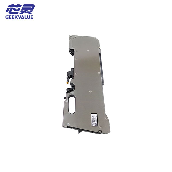
A maximum X3 S configuration provides up to 160 positions for standard 8 mm SIPLACE X feeders. Wider feeders occupy several 8 mm positions and reduce the number of physical feeder units that can be installed.
Number of component trolleys included
Number of included 8 mm feeders
Quantity of 12 mm, 16 mm and wider feeders
Feeder generation and part number
Feeder firmware compatibility
Machine-software compatibility
Feeder calibration status
Tape-indexing and pickup performance
Trolley docking and communication condition
Reel holders and waste-tape containers
Feeders and component trolleys are not automatically included with every used machine. The quotation should list the machine, heads, trolleys, feeders, nozzles and tray systems separately.
A used X3 S may have a single conveyor or flexible dual conveyor. PCB capacity depends on the conveyor generation, installed width package and long-board options.
Later platform specifications describe board sizes from approximately 50 × 50 mm to 850 × 685 mm. Earlier specifications commonly list 450 × 560 mm as a standard single-conveyor format and up to 850 × 560 mm with a Long Board Option.
Minimum PCB length and width
Maximum PCB or panel dimensions
PCB thickness
Maximum assembled-board weight
Single-lane or dual-lane production
Same or different products on each lane
Required PCB transport direction
Fixed conveyor-rail position
Required line height
PCB edge-clearance requirement
Long-board or wide-board requirement
PCB support and warpage-control requirement
Interface with the surrounding SMT equipment
The maximum platform PCB dimension should not be assigned automatically to every used X3 S. Request physical measurements and a powered-on board-transport test.
The words used, inspected and refurbished should describe different supply conditions.
| Supply Condition | Typical Scope | Information to Request |
|---|---|---|
| Used machine | Supplied largely in its current condition | Power-on video, alarm status, operating hours and included accessories |
| Inspected machine | Core systems checked under powered-on conditions | Inspection list, test video and identified defects |
| Refurbished machine | Selected worn or failed parts serviced or replaced | Refurbishment record, replacement-part list and final acceptance test |
A repainted exterior does not prove that a machine has been refurbished. The refurbishment scope should identify the inspected, repaired, calibrated and replaced items.
Complete X3 S model designation
Machine item and serial numbers
Manufacturing year
Total operating hours
Total placement counter
Original factory configuration
Current installed configuration
Station-software version
Programming-software compatibility
Movement of all three gantries
X-axis and Y-axis noise
Vibration during acceleration and deceleration
Machine homing and reference operation
Linear-motor condition
Encoder and position-feedback condition
Axis-drive alarm history
Cable-chain and trailing-cable condition
Gantry alignment and calibration
Head installed on gantry one
Head installed on gantry two
Head installed on gantry three
Head model, part number and serial number
Individual head operating hours
Individual placement counters
Installed camera type
Nozzle-changer configuration
Maintenance and repair history
Nozzle-segment and sleeve condition
Z-axis movement
Rotational-axis movement
Vacuum pressure and leakage
Component-presence sensors
Placement-force monitoring
Nozzle-changer operation
Special nozzle or gripper operation
Pickup and placement repeatability
Abnormal head temperature or noise
Component camera on all three gantries
PCB-camera image quality
Lighting-level operation
Component-shape recognition
Small-component recognition
Fiducial recognition
Pickup-position correction
PCB warpage measurement
Coplanarity inspection where installed
Camera calibration status
Single or flexible dual conveyor
Synchronous and asynchronous operation
Automatic width adjustment
Conveyor belts and pulleys
PCB entrance and exit sensors
PCB clamping and support
Long-board and wide-board options
Maximum measured PCB format
Communication with surrounding equipment
Number of included component trolleys
Number and type of included feeders
Feeder tape-width combinations
Feeder firmware compatibility
Feeder indexing and pickup performance
Trolley docking and locking condition
Communication-interface operation
Reel holders and tape-waste containers
Material setup-verification functions
Matrix Tray Changer availability
Waffle Pack Changer availability
Tray elevator and transfer operation
Special component-supply modules
Required nozzles and grippers
Pickup-position calibration
Snap-in or placement-force functions where required
Station computers and monitors
Machine-software backups
Product and configuration files
Nozzles and nozzle magazines
Component trolleys and feeders
Tray systems
Transformer or voltage-conversion equipment
Operating and maintenance manuals
Calibration tools
Included spare parts
A complete acceptance test should demonstrate more than startup and gantry movement.
Start the machine from a complete power-off condition.
Record the machine model, serial number and software version.
Complete the homing and reference sequence.
Operate all three gantries through their full movement range.
Show the label of every installed placement head.
Test feeder communication and component indexing.
Perform component pickup with each head.
Demonstrate component-camera recognition.
Test the PCB camera and fiducial recognition.
Operate the nozzle changers.
Transport a representative PCB through the conveyor.
Run a sample placement program.
Record alarms, rejected components and pickup retries.
Show the final machine status after the test.
CP20 or SpeedStar head segments
CPP or MultiStar head assemblies
TWIN or TwinHead Z-axis assemblies
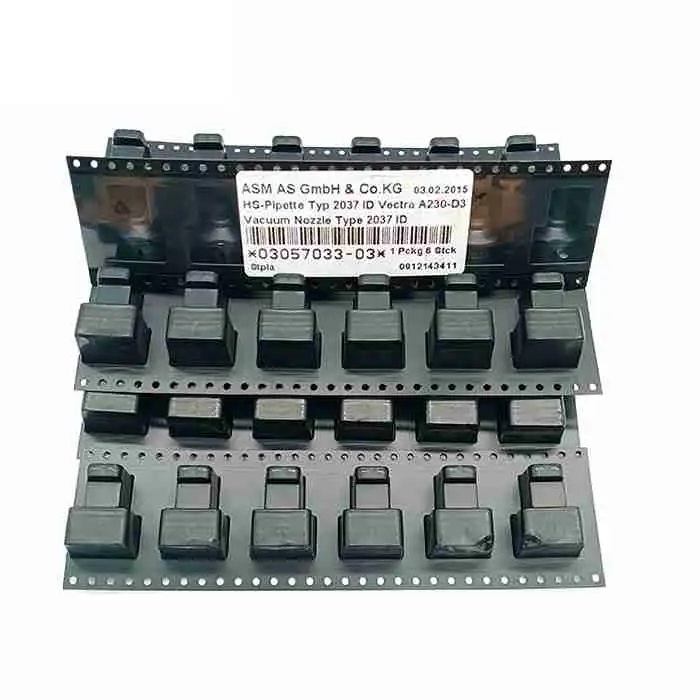
Nozzle sleeves and nozzle holders
Nozzles and nozzle changers
Vacuum valves, generators and filters
Placement-force and component sensors
Component cameras and lighting modules
PCB camera and fiducial lighting
Linear motors and encoders
Axis drives and control boards
Trailing cables and cable chains
Cooling fans and machine filters
Conveyor belts, pulleys and sensors
PCB support and warpage systems
Component-trolley docking interfaces
SIPLACE X feeders
Station computers and storage devices
Refurbishment should be based on inspection results. Replacing parts without completing calibration and placement testing does not confirm production readiness.
A SIPLACE X3 S is a precision machine. Gantries, heads, conveyors, computers and feeder interfaces must be secured correctly before transport.
Complete machine backup
Parking and securing of all three gantries
Head and nozzle protection
Removal or securing of component trolleys
Protection of monitors and station computers
Moisture and impact protection
Vacuum packaging where required
Suitable export crate or container fixing
Photographs before and after packaging
Complete packing list
Factory voltage and frequency
Compressed-air pressure and quality
Machine installation space
Floor loading and levelling conditions
Upstream and downstream line height
PCB transport direction
Network and factory-software requirements
Available feeder and nozzle inventory
Installation and calibration support requirements
A used SIPLACE X3 S may be suitable when:
An existing X3 S requires direct replacement
The factory needs more output than an X2 S provides
An X4 S is not required for the target production capacity
The existing line already uses X-Series S equipment
The factory owns compatible SIPLACE X feeders
Existing product programs are based on SIPLACE software
Operators and technicians understand the platform
The PCB contains both small components and medium IC packages
Production capacity must be expanded with limited process changes
A used-equipment investment is preferred over a new platform
Replacement or line-expansion purpose
Required manufacturing year
Preferred used, inspected or refurbished condition
Required placement-head combination
Target production output
Smallest component package
Largest component dimensions
Maximum component height and weight
Required placement accuracy
Required placement force
PCB dimensions and thickness
Single- or dual-conveyor requirement
Long-board or wide-board requirement
Required feeder quantity and tape widths
Existing feeder model and generation
Tray or special component-supply requirement
Current SIPLACE line configuration
Machine software and factory-interface requirements
Factory voltage and frequency
Destination country
Required delivery schedule
Yes. The X3 S has three placement gantries. The X2 S has two gantries, while the X4 S and X4i S have four.
The X-Series S platform provides separate X2 S, X3 S and X4 S models. A standard X3 S should be treated as a three-gantry machine and verified from its nameplate.
Later specifications list up to approximately 112,500 CPH benchmark and 97,050 CPH IPC performance. Earlier specifications list 127,875 CPH theoretical, 94,500 CPH benchmark and 78,100 CPH IPC performance.
The values come from different head, software and machine generations. The exact equipment configuration must be checked before a speed rating is assigned.
Later configurations may use CP20, CPP and TWIN heads. Earlier documentation may use SpeedStar, MultiStar and TwinHead names.
The machine can provide up to 160 positions for standard 8 mm SIPLACE X feeders. Wider feeders occupy multiple positions.
Not automatically. Feeders, component trolleys, nozzles, tray systems and spare parts may be included or quoted separately.
It may be suitable as a direct replacement, but the heads, conveyor, software, transport direction, voltage and line interfaces must be matched.
PCB capability depends on the conveyor and installed options. Later platform data extends to approximately 850 × 685 mm, while earlier standard configurations may support smaller formats.
It should show startup, homing, all three gantries, every head label, feeder pickup, component recognition, nozzle changes, PCB transport and an actual placement program.
A used machine may be supplied largely in its current condition. A refurbished machine should have a documented inspection, repair, replacement and calibration scope.
Provide the required head combination, PCB dimensions, component range, output target, feeder package, software environment, factory voltage and destination.
Send your current line configuration, required placement heads, PCB dimensions, component range, feeder inventory, target output and destination country. GEEKVALUE will check available SIPLACE X3 S machines and confirm the machine label, manufacturing year, serial number, installed heads, conveyor, software, operating condition, included accessories and inspection scope.
Review the ASM SIPLACE X3 S technical page, compare the complete SIPLACE X S / XS Series, or explore compatible SIPLACE X feeders, placement heads and SMT nozzles.
If you are not sure whether this product matches your machine, send us the model, label photo or old part picture for checking.