Used Siemens ASM SIPLACE D1 flexible SMT mounter with modular C&P and P&P heads, 90 feeder tracks and tray support.
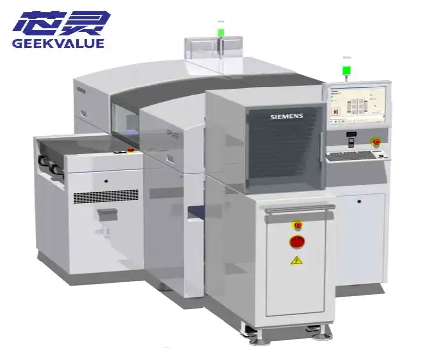
The Siemens ASM SIPLACE D1 placement machine is a flexible single-gantry SMT mounter designed to process standard chips, integrated circuits, fine-pitch packages, tray-fed devices and selected large or odd-shaped components. Its modular head architecture allows the machine to combine a high-speed Collect & Place head with a precision Pick & Place head according to the production requirement.
Unlike a dedicated high-speed chip shooter, the SIPLACE D1 is intended to provide a balanced combination of placement flexibility, component-range coverage and precision. It can operate as a standalone mounter in a high-mix line or as the flexible placement module positioned after a faster chip-placement machine.
GEEKVALUE supplies available used, inspected and refurbished SIPLACE D1 machines according to the installed placement heads, conveyor configuration, feeder tables, tray system, software version and machine condition. Explore the complete Siemens ASM SIPLACE D Series to compare D1, D1i, D2, D2i, D3, D3i, D4 and D4i configurations.
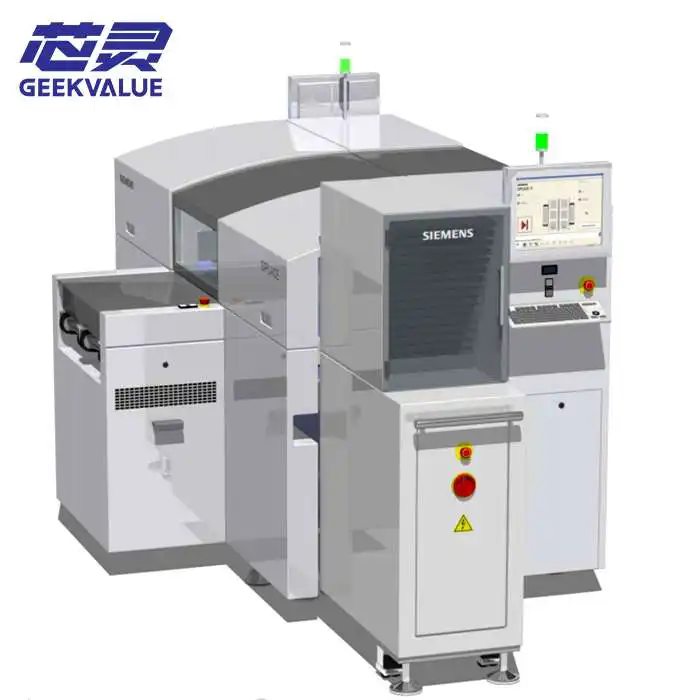
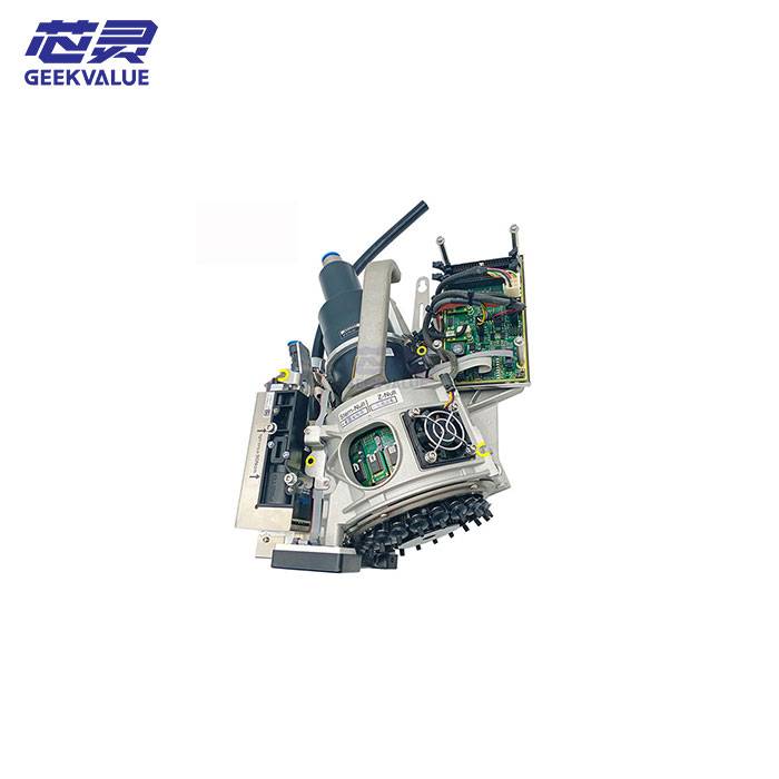
The SIPLACE D1 uses one X/Y gantry that can carry one or two placement heads. Depending on the original machine configuration, the gantry may be equipped with a 12-nozzle Collect & Place head, a 6-nozzle Collect & Place head, a precision Pick & Place head or a combination of Collect & Place and Pick & Place heads.
This modular arrangement allows the D1 to process small passive components and standard SMD packages while also handling larger ICs, fine-pitch components and specialized devices that require greater placement accuracy or controlled placement force.
Flexible single-gantry SMT placement platform
One- or two-head machine configurations
12-nozzle Collect & Place head option
6-nozzle Collect & Place head option
High-precision Pick & Place head option
Component range from approximately 0.6 × 0.3 mm to 85 × 85 mm
Selected components up to approximately 200 × 125 mm with restrictions
Up to 90 tracks for 8 mm tape feeders
Single-conveyor and flexible dual-conveyor options
Optional waffle-pack tray and automatic tray-changing systems
| Specification | Typical SIPLACE D1 Configuration |
|---|---|
| Machine type | Flexible single-gantry SMT placement machine |
| Number of gantries | 1 |
| Available placement heads | C&P12, C&P6 and Pick & Place Head |
| C&P12 benchmark speed | Up to approximately 15,000 CPH |
| C&P6 benchmark speed | Up to approximately 9,800 CPH |
| Pick & Place Head benchmark speed | Up to approximately 2,400 CPH |
| Overall component range | Approximately 0.6 × 0.3 mm to 85 × 85 mm |
| Extended component range | Selected components up to approximately 200 × 125 mm with restrictions |
| Maximum component height | C&P12: approximately 6 mm; C&P6: approximately 8.5 mm; P&P: approximately 19 mm |
| Best specified placement accuracy | Up to approximately ±30 μm at 3 sigma or ±40 μm at 4 sigma with the appropriate P&P vision configuration |
| Maximum feeder capacity | Up to 90 tracks for 8 mm tape feeders |
| Feeder tables | Up to two component changeover tables |
| Single-conveyor PCB size | Approximately 50 × 50 mm to 460 × 460 mm |
| Single-conveyor long-board option | Up to approximately 610 × 460 mm |
| Flexible dual-conveyor PCB size | Approximately 50 × 50 mm to 460 × 216 mm per lane |
| PCB thickness | Approximately 0.3–4.5 mm; other thicknesses may require confirmation |
| Component supply | Tape, bulk case, stick magazine, tray, waffle pack and application-specific feeders |
| Typical production role | Flexible placement of mixed SMD, IC, fine-pitch and tray-fed components |
Configuration notice: SIPLACE D1 machines were supplied with different head combinations, cameras, conveyors, feeder tables, electrical specifications and software generations. The actual capability of a used machine must be confirmed from its nameplate, installed hardware and powered-on inspection.
The installed placement-head combination is the most important factor when evaluating a used SIPLACE D1. Two machines with the same D1 model designation may be suitable for completely different production applications.
Common D1 head arrangements include:
C&P12 head plus Pick & Place Head
C&P6 head plus Pick & Place Head
C&P12 head only
C&P6 head only
Pick & Place Head only
A machine equipped with both a Collect & Place head and a Pick & Place head provides the broadest component coverage. A single-head configuration may be appropriate when the machine has a clearly defined role within an existing line.
The C&P12 head is designed for higher-speed placement of small and medium standard components. Twelve nozzle positions are arranged around a rotary head assembly, allowing several components to be collected before the head moves to the PCB.
Components are picked from the stationary feeder table, inspected by the vision system, corrected for position and rotation, and then placed on the stationary PCB.
| Typical component range | Approximately 0.6 × 0.3 mm to 18.7 × 18.7 mm |
|---|---|
| Maximum component height | Approximately 6 mm |
| Benchmark placement rate | Up to approximately 15,000 CPH |
| Standard-camera accuracy | Approximately ±67.5 μm at 3 sigma or ±90 μm at 4 sigma |
| High-resolution-camera accuracy | Approximately ±60 μm at 3 sigma or ±80 μm at 4 sigma |
The C&P12 configuration is commonly used for chip resistors, capacitors, diodes, transistors, small IC packages and other tape-fed SMD components.
The C&P6 head provides greater component flexibility than the 12-nozzle head while retaining the multi-nozzle collection principle. Its six nozzle positions support larger IC packages and components that require more clearance or specialized nozzles.
| Typical component range | Approximately 1.6 × 0.8 mm to 32 × 32 mm, depending on vision and tooling |
|---|---|
| Maximum component height | Approximately 8.5 mm |
| Benchmark placement rate | Up to approximately 9,800 CPH |
| Specified placement accuracy | Approximately ±52.5 μm at 3 sigma or ±70 μm at 4 sigma |
This head may be selected for PLCC, QFP, BGA, CSP and other medium-sized packages that do not require the full component capacity of the Pick & Place head.
The SIPLACE Pick & Place head processes components individually. It is intended for fine-pitch ICs, large packages, heavy devices, tray-fed components and selected odd-shaped parts.
Its lower nominal placement speed is balanced by greater accuracy, component-size capacity and placement-force control.
| Standard component range | Up to approximately 85 × 85 mm |
|---|---|
| Extended component capability | Selected components up to approximately 200 × 125 mm with restrictions |
| Maximum component height | Approximately 19 mm |
| Benchmark placement rate | Up to approximately 2,400 CPH |
| Fine-pitch-camera accuracy | Approximately ±37.5 μm at 3 sigma or ±50 μm at 4 sigma |
| Flip-chip-camera accuracy | Approximately ±30 μm at 3 sigma or ±40 μm at 4 sigma |
The actual maximum component size depends on package geometry, weight, height, pickup surface, nozzle or gripper design, camera field of view and available feeder presentation.
The D1 does not focus exclusively on maximum small-component speed. Its production value comes from the ability to process a broad mixture of components using different placement methods within one machine.
The Collect & Place head can install standard components efficiently, while the Pick & Place head completes larger or more demanding devices. This reduces the need to assign every specialized component to a separate machine.
The platform may be suitable for:
High-mix PCB assembly
Medium-volume electronics production
Industrial-control PCB manufacturing
Automotive electronic modules
Telecommunications equipment
Medical electronic assemblies
Fine-pitch IC placement
Tray-fed component placement
Legacy SIPLACE line expansion
End-of-line flexible placement
During placement, the PCB is held stationary within the placement area, while the component feeder tables also remain stationary. The gantry moves between the feeders, vision system and PCB coordinates.
This operating principle provides several practical benefits:
Stable component pickup positions
Reduced risk of component movement on the PCB
Reliable pickup of small components
Consistent optical inspection before placement
Reduced unnecessary head travel
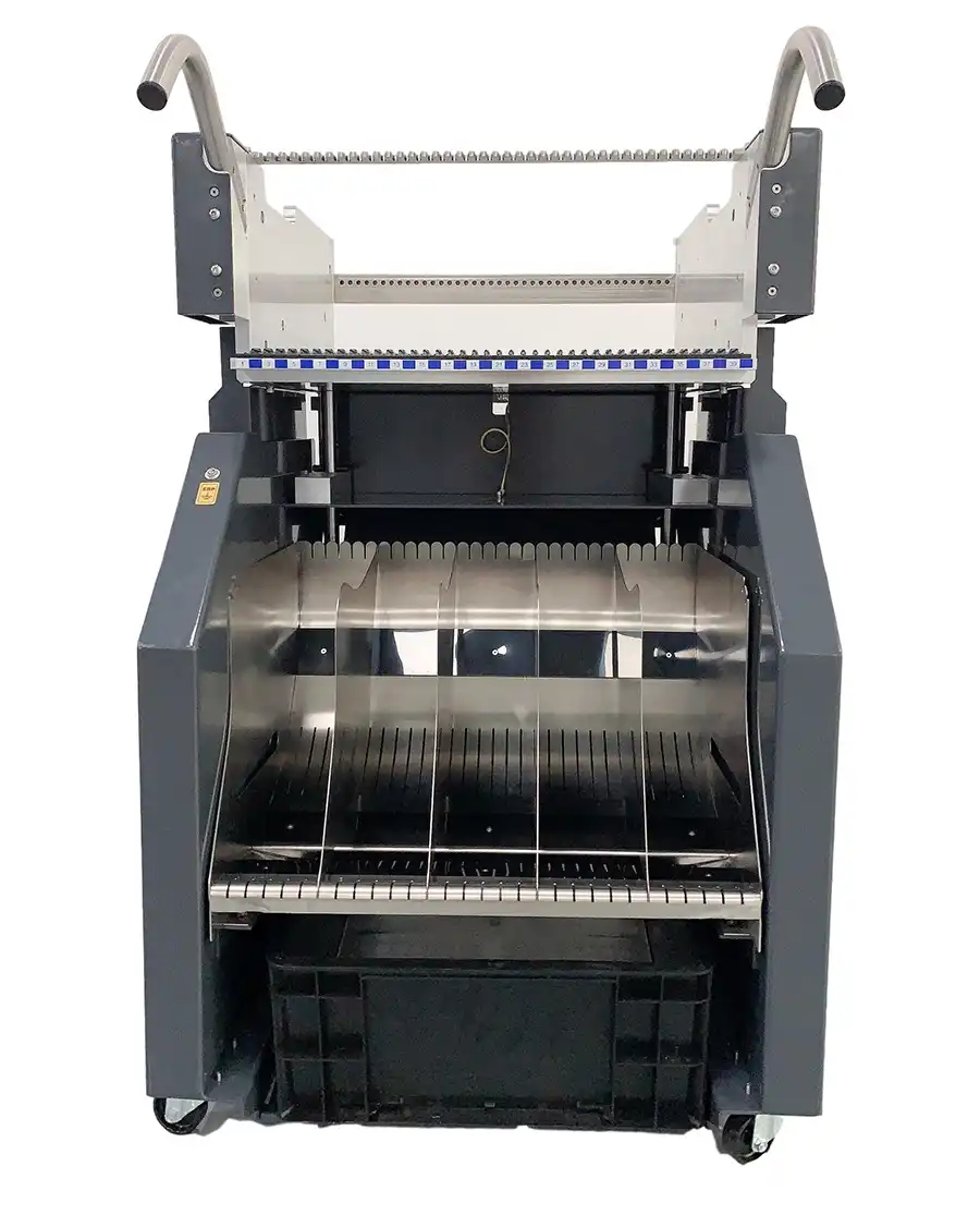
Feeders can be refilled or tape can be spliced without moving the complete feeder table
The actual production rate still depends on component distribution, feeder positions, nozzle changes, tray access, PCB dimensions and the proportion of placements assigned to the slower Pick & Place head.
The SIPLACE D1 can use up to two removable component changeover tables. Each table provides up to fifteen standard feeder-module locations.
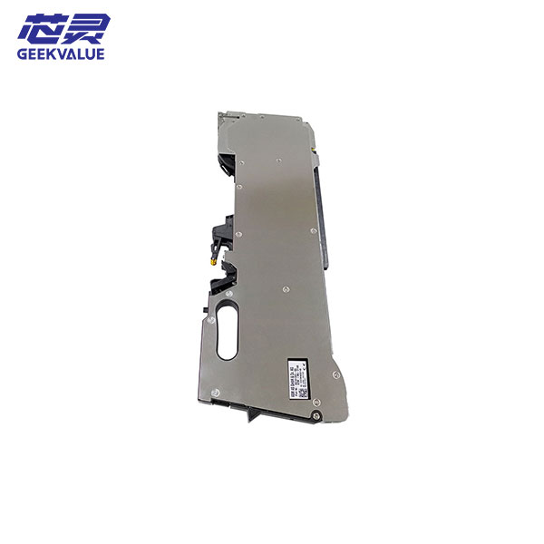
When the machine is configured with 3 × 8 mm S feeder modules, total capacity can reach approximately 90 individual 8 mm tape tracks.
Different feeder widths change the total capacity:
| Feeder Configuration | Approximate Maximum Capacity |
|---|---|
| 3 × 8 mm S feeder modules | 90 tracks |
| 2 × 8 mm S feeder modules | 60 tracks |
| 12/16 mm feeder modules | 30 modules |
| 24/32 mm feeder modules | 20 modules |
| 44 mm feeder modules | 14 modules |
| 56 mm feeder modules | 12 modules |
| 72 mm feeder modules | 10 modules |
| 88 mm feeder modules | 8 modules |
The maximum feeder count should not be interpreted as the number of feeders automatically included with a used machine. Feeders, changeover tables, reel holders and waste-tape containers must be listed clearly in the quotation.
Depending on the installed hardware, the D1 can work with:
8 mm to 88 mm tape feeder modules
Paper and embossed carrier tapes
Bulk-case feeders
Vibratory stick feeders
Manual waffle-pack tray holders
Automatic Waffle Pack Changer systems
Surf Tape feeder modules
Application-specific OEM feeders
Tray-fed ICs and specialized components can be supplied through a manual waffle-pack tray holder or an automatic Waffle Pack Changer.
A manual tray holder may be sufficient when only a small number of tray-supplied components are required. An automatic tray changer is more suitable when the program uses several component types or requires continuous tray exchange during production.
Before purchasing a machine for tray production, confirm:
Whether a Waffle Pack Changer is physically installed
Supported tray dimensions
Number of tray levels or magazines
Tray elevator and transfer condition
Communication with the placement-machine software
Component pickup position and calibration
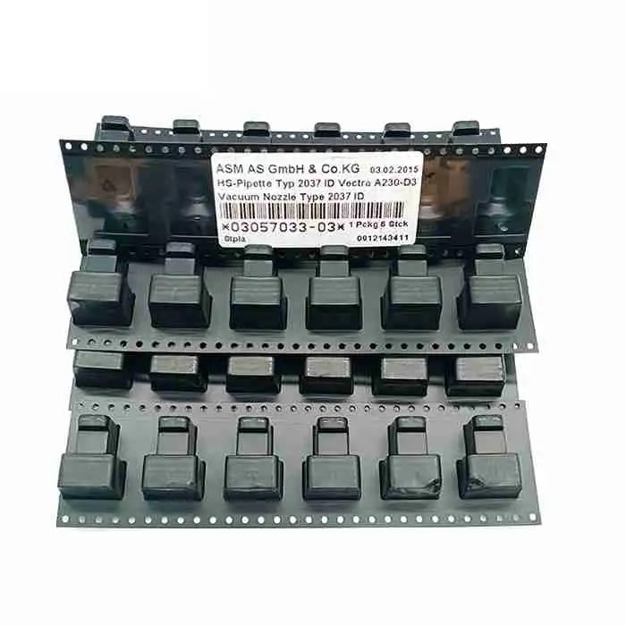
Availability of the required nozzles or grippers
SIPLACE D1 machines may have a single conveyor or a flexible dual conveyor. Conveyor configuration must be verified on the actual machine because it affects PCB width, line balancing and compatibility with upstream and downstream equipment.
A common single-conveyor D1 supports PCB sizes from approximately 50 × 50 mm to 460 × 460 mm. Machines with a long-board option may process boards up to approximately 610 × 460 mm.
A wide-board configuration may increase supported PCB width, but surrounding printers, inspection systems, reflow ovens and board-handling equipment must also support the wider panel.
A common flexible dual-conveyor configuration supports PCB sizes from approximately 50 × 50 mm to 460 × 216 mm per lane. Long-board-equipped machines may support lengths up to approximately 610 mm.
The flexible dual conveyor can also be operated in a wider single-conveyor mode on suitable configurations. This allows the factory to switch between two narrower production lanes and one wider PCB stream.
Minimum and maximum PCB length
Minimum and maximum PCB width
PCB thickness
Maximum PCB or panel weight
Single- or dual-lane production requirement
Fixed conveyor-rail position
Transport direction
Production-line height
SMEMA or Siemens interface requirement
Long-board or wide-board requirement
The D1 should not be selected based on one CPH number alone. Each placement head has a different benchmark rate, and real production output depends on the component assignment.
A board dominated by small components assigned to the C&P12 head may achieve a relatively high output. A board containing many large, fine-pitch or tray-fed components assigned to the Pick & Place head will have a lower but more precision-focused cycle rate.
Factors affecting actual D1 output include:
Installed head combination
Number of placements assigned to each head
Feeder locations
Tray access time
Component inspection requirements
Nozzle-change frequency
PCB size and panel arrangement
Conveyor loading and unloading time
Component pickup retries
Program and line optimization
For an accurate production assessment, the PCB BOM, component list, placement coordinates and target cycle time should be reviewed instead of relying only on the theoretical machine rating.
The D1 can be used as a standalone flexible machine in a lower-volume line or installed after a high-speed mounter that handles most small components.
A typical production arrangement may include:
PCB loader
Solder paste printer
Solder paste inspection system
High-speed chip mounter
SIPLACE D1 flexible placement machine
Reflow oven
Automatic optical inspection system
PCB unloader
In this arrangement, the faster mounter installs resistors, capacitors and other standard components. The D1 then handles larger ICs, tray-fed devices, fine-pitch packages and components requiring greater placement control.
The complete line must be balanced carefully. The D1 may become the cycle-time bottleneck when too many components are assigned to the Pick & Place head.
| Comparison | SIPLACE D1 | SIPLACE D1i |
|---|---|---|
| Platform position | Original flexible single-gantry D Series model | Later single-gantry D Series generation |
| Typical head options | C&P12, C&P6 and Pick & Place | C&P12, C&P6 and Pick & Place |
| Smallest published component | Approximately 0201 inch with the relevant package | Down to 01005 metric with the relevant configuration |
| Published D1i performance values | Head-specific benchmark values should be checked | 13,000 CPH IPC, 15,000 CPH benchmark and 20,000 CPH theoretical |
| Selection requirement | Verify the actual machine label, head setup and software | Verify the actual machine label, head setup and software |
D1 and D1i should not be treated as identical machines. A supplier listing may omit the “i” or use a shortened model description, so the machine nameplate and software information must be checked before quotation.
A used D1 should be assessed as a complete placement system rather than only by its appearance or manufacturing year. Machine condition, head configuration, camera type, conveyor arrangement and included accessories determine its real production value.
Complete model designation
D1 or D1i confirmation
Machine serial number
Manufacturing year
Total operating hours
Total placement counter
Original and current machine configuration
Machine-software and station-computer version
X-axis and Y-axis movement
Machine homing and reference operation
Abnormal axis noise or vibration
Motor and encoder condition
Drive-module alarms
Cables and cable-chain condition
Guide-rail and lubrication condition
Gantry alignment and calibration
Exact C&P12, C&P6 or P&P head configuration
Head identification labels
Head operating and placement counters
Nozzle-sleeve wear
Rotary-star movement
Z-axis and rotational-axis condition
Vacuum pressure and leakage
Component-sensor operation
Nozzle-changer operation
Pickup and placement repeatability
PCB camera image quality
Component camera type
Standard or high-resolution vision configuration
Fine-pitch or flip-chip camera availability
Lighting-level operation
Fiducial recognition
Component-shape recognition
Camera calibration status
Single or flexible dual conveyor
Automatic width adjustment
Transport direction
Conveyor-belt condition
PCB entrance and exit sensors
Board clamping and support
Long-board function where required
Communication with surrounding machines
Number of component changeover tables
Included feeder quantities and tape widths
Feeder-table locking condition
Communication connectors
Reel holders and waste containers
Manual tray-holder availability
Waffle Pack Changer condition
Tray elevator and transfer operation
Station computer and monitor
Machine software and backup files
Nozzles and nozzle changers
Feeders and component tables
Tray equipment
Transformer or voltage accessories
Operating manuals
Maintenance tools
Available spare parts
A powered-on inspection video should show machine startup, homing, gantry movement, every installed placement head, feeder pickup, component recognition, nozzle changing, PCB conveyor operation and a sample placement program.
Long-term operation of a legacy SIPLACE D1 depends on preventive maintenance and access to compatible replacement parts.
Important inspection and service areas include:
Collect & Place head segments and sleeves
Pick & Place head Z-axis and rotational assemblies
Nozzles, nozzle holders and nozzle changers
Vacuum valves and pneumatic components
Component cameras and lighting modules
PCB camera and fiducial lighting
X/Y motors and encoders
Axis drives and control boards
Flat cables and machine wiring
Compressed-air filters
Cooling fans and air filters
Conveyor belts, pulleys and sensors
Component-table docking connectors
Feeder modules and tape cutters
Station computer and storage devices
Maintenance should include head cleaning, nozzle inspection, vacuum testing, camera calibration, conveyor adjustment, feeder calibration, filter replacement and verification of software backups.
A used D1 may be a practical option for manufacturers that already operate legacy SIPLACE equipment and require additional flexible-placement capacity.
The machine may be suitable when:
The factory already owns compatible SIPLACE S feeders
The PCB contains a mixture of small and large components
Tray-fed ICs must be processed
Fine-pitch placement is required
Existing technicians understand SIPLACE D Series operation
Legacy software and spare-parts support are available
A damaged D1 must be replaced without redesigning the complete line
A lower equipment investment is preferred
A newer placement platform may be more appropriate when the project requires current MES integration, very high throughput, newer feeder technology, lower energy consumption or long-term original-manufacturer lifecycle support.
Provide the following information so the available machine can be matched to the production requirement:
Required D1 or D1i model
Preferred machine condition
Required C&P12, C&P6 or Pick & Place head
Minimum and maximum component size
Maximum component height and weight
Required placement accuracy
PCB dimensions and thickness
Single- or dual-conveyor requirement
Required tape-feeder quantities
Required feeder tape widths
Tray or Waffle Pack Changer requirement
Need for special nozzles or grippers
Existing SIPLACE line configuration
Factory voltage and frequency
Destination country
Required delivery schedule
For unusual components, send the package drawing, dimensions, weight, pickup-surface image, feeder presentation and placement-force requirements for preliminary evaluation.
The SIPLACE D1 is a flexible SMT placement machine used for standard SMD components, integrated circuits, fine-pitch packages, tray-fed devices and selected large or odd-shaped components.
The D1 has one X/Y placement gantry. Depending on the machine configuration, the gantry can carry one or two placement heads.
Common head options include a 12-nozzle Collect & Place head, a 6-nozzle Collect & Place head and a high-precision Pick & Place head.
The published benchmark rate depends on the installed head. The C&P12 head provides up to approximately 15,000 CPH, the C&P6 head approximately 9,800 CPH and the Pick & Place head approximately 2,400 CPH.
Yes. A properly configured D1 can process components down to approximately 0.6 × 0.3 mm, commonly described as 0201-inch components. The correct feeder, nozzle, camera package and machine condition are required.
The Pick & Place head commonly supports components up to approximately 85 × 85 mm. Selected components up to approximately 200 × 125 mm may be possible with restrictions and suitable tooling.
The machine can provide up to approximately 90 individual 8 mm tracks when configured with two component tables and 3 × 8 mm S feeder modules. Wider feeders reduce the total installed quantity.
Yes. The machine can use manual waffle-pack tray holders or an optional automatic Waffle Pack Changer, depending on the installed configuration.
The D1i is a later D Series generation with updated capabilities and published support for smaller 01005 metric components. The two models should be distinguished using the machine nameplate, software version and installed hardware.
Not automatically. Feeders, component tables, nozzles, tray systems and spare parts may be included or quoted separately. Every included item should be listed in the quotation.
Test the gantry, every installed placement head, component cameras, PCB camera, nozzle changers, vacuum system, conveyor, feeder interfaces, tray system and station computer. A sample placement test is strongly recommended.
Send your required head configuration, PCB dimensions, component range, feeder quantity, tray requirement, target output and destination country. GEEKVALUE will check available Siemens ASM SIPLACE D1 machines and confirm the serial number, manufacturing year, placement heads, cameras, conveyor configuration, included accessories, inspection scope and delivery arrangement.
View the complete SIPLACE D Series placement machine range, or explore compatible SIPLACE SMT feeders, placement heads and SMT nozzles.
If you are not sure whether this product matches your machine, send us the model, label photo or old part picture for checking.