










The ASM SIPLACE TX2 placement machine is a compact dual-gantry SMT mounter designed for high-output electronics production without requiring excessive line space. With benchmark placement performance of up to 85,500 components per hour, the TX2 provides a practical balance between small-component speed, flexible IC placement and support for selected large or odd-shaped components.
The actual production capability of a SIPLACE TX2 depends on its two installed placement heads. A machine equipped with two CP20 high-speed heads is optimized for small-component volume production, while configurations using CPP or TWIN heads provide a broader component range and more flexible placement functions.
GEEKVALUE supplies available used, inspected and refurbished SIPLACE TX2 machines according to the machine year, head configuration, conveyor arrangement, feeder package, software version and equipment condition. Explore the complete ASM SIPLACE TX Series to compare TX1, TX2 and TX2i placement platforms.
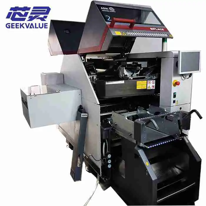
ASM SIPLACE TX2 Machine Overview
The SIPLACE TX2 is the standard two-head model within the compact TX placement platform. It is positioned between the single-head TX1 and the higher-output TX2i.
Although the machine occupies only approximately one metre of production-line length, it can accommodate up to 80 positions for standard 8 mm tape feeders and process a wide component spectrum when fitted with the appropriate placement heads.
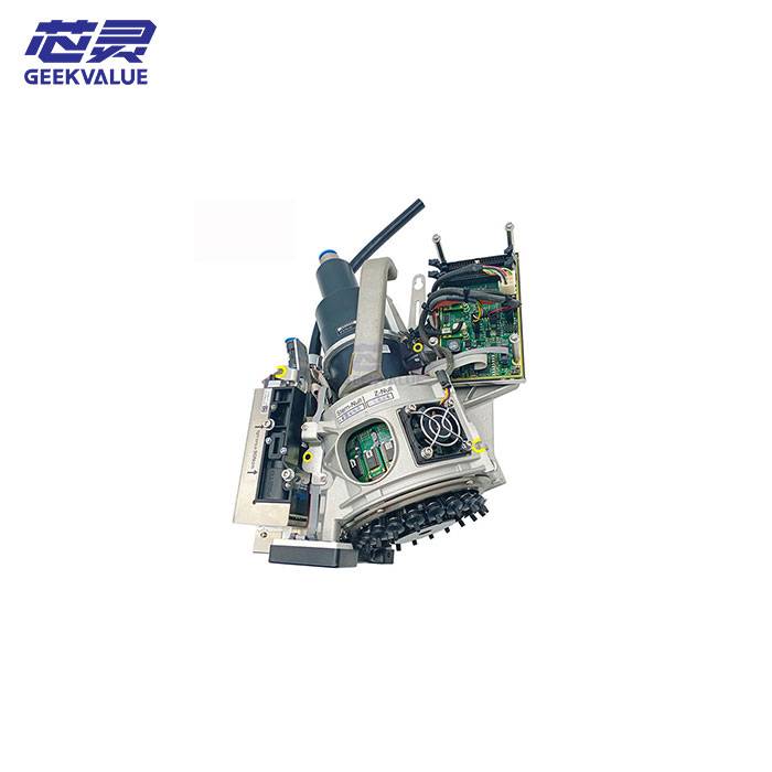
Available head options include the CP20 for maximum small-component speed, the CPP for flexible mixed-component production and the TWIN head for larger, heavier or odd-shaped components.
Compact dual-gantry SMT placement platform
Benchmark placement performance up to 85,500 CPH
Approximately one metre of production-line length
CP20, CPP and TWIN placement-head options
Up to 80 positions for standard 8 mm tape feeders
Single-lane and dual-lane PCB production
Component spectrum from approximately 0.12 × 0.12 mm to 200 × 110 mm
Placement accuracy down to approximately 22 μm at 3 sigma with the relevant head
Touchless and low-force placement options
Support for tape, tray, dipping and application-specific component supply
Suitable for medium- and high-volume SMT production
ASM SIPLACE TX2 Technical Specifications
| Specification | Typical SIPLACE TX2 Platform Capability |
|---|---|
| Machine type | Compact dual-gantry SMT placement machine |
| Machine model | ASM SIPLACE TX2 |
| Number of placement gantries | 2 |
| Available placement heads | CP20, CPP and TWIN, depending on machine generation and configuration |
| Benchmark placement speed | Up to approximately 85,500 CPH |
| Overall component spectrum | Approximately 0.12 × 0.12 mm to 200 × 110 mm, depending on installed heads |
| Maximum component height | Up to approximately 25 mm with the TWIN head |
| Best published placement accuracy | Approximately 22 μm at 3 sigma with the relevant TWIN configuration |
| Feeder capacity | Up to 80 positions for standard 8 mm tape feeders |
| Minimum PCB size | Approximately 50 × 45 mm |
| Standard maximum PCB length | Approximately 375 mm without the Long Board Option |
| Single-lane PCB size | Up to approximately 590 × 460 mm with the Long Board Option |
| Dual-lane PCB size | Up to approximately 590 × 260 mm per lane with the Long Board Option |
| Machine dimensions | Approximately 1.00 × 2.47 × 1.45 m |
| Typical power consumption | Approximately 2.0 kW with vacuum pump or 1.2 kW without vacuum pump |
| Component supply | Tape feeders, JEDEC trays, SIPLACE Tray Unit, Linear Dipping Unit, Glue Feeder and application-specific systems |
| Typical production role | High-output small-component placement and mixed-component SMT production |
Configuration notice: The specifications above describe the general SIPLACE TX platform and common TX2 configurations. The exact speed, component spectrum, placement accuracy, PCB dimensions and feeder package of an individual machine must be confirmed from its nameplate, installed heads, conveyor system and software.
TX2 Is Not the Same as TX2i
The SIPLACE TX2 and TX2i belong to the same compact placement platform, but they have different published performance ratings and machine dimensions.
Used-equipment listings sometimes omit the letter “i” or apply the 96,000 CPH TX2i speed to a standard TX2. The complete machine nameplate must therefore be checked before a specification or quotation is confirmed.
| Comparison | SIPLACE TX1 | SIPLACE TX2 | SIPLACE TX2i |
|---|---|---|---|
| Platform position | Compact single-head configuration | Standard dual-head configuration | Highest-output dual-head configuration |
| Benchmark placement speed | Up to 44,000 CPH | Up to 85,500 CPH | Up to 96,000 CPH |
| Machine dimensions | Approximately 1.00 × 2.35 × 1.45 m | Approximately 1.00 × 2.47 × 1.45 m | Approximately 1.00 × 2.23 × 1.45 m |
| Maximum 8 mm feeder positions | Up to 80 | Up to 80 | Up to 80 |
| Head options | CP20, CPP or TWIN, depending on configuration | CP20, CPP or TWIN combinations | Primarily high-output two-head configurations |
| Selection priority | Lower output or specialized placement role | Balanced high output and flexibility | Maximum compact-platform throughput |
The TX2 should therefore be published with an 85,500 CPH benchmark rating. The 96,000 CPH value belongs to the TX2i and should not be reused on a standard TX2 product page.
Understanding the 85,500 CPH Placement Rating
The 85,500 CPH figure is a benchmark performance value for a suitable high-speed TX2 configuration. It is not guaranteed production output for every PCB program.
Actual throughput depends on the two installed heads, component mix, feeder arrangement, PCB dimensions and complete SMT line balance.
Factors That Affect Actual TX2 Output
Placement head installed on each gantry
Total number of placements per PCB
Distribution of placements between the two heads
Feeder location and component tape width
PCB dimensions and panel arrangement
Component inspection and rotation requirements
Number of nozzle changes
Tray or special component-supply time
Conveyor loading and unloading cycle
Pickup retries and component rejection rate
Placement-head, nozzle and feeder condition
PCB support and warpage
Production-program optimization
Printer, reflow oven and inspection-system cycle times
A realistic production estimate should be calculated using the actual BOM, placement file, feeder arrangement and target cycle time instead of dividing the component quantity by 85,500.
Compact Output Without a Long Placement Line
One of the main advantages of the SIPLACE TX platform is its output per metre of production-line length. The TX2 occupies approximately one metre along the line while providing two placement gantries and up to 80 feeder positions.
This compact format is useful when a manufacturer needs to increase placement capacity but has limited floor space or wants to keep the complete line relatively short.
Benefits of the Compact TX2 Format
Add production capacity without significantly extending the line
Improve output per square metre of factory space
Provide feeder capacity on both sides of a compact machine
Maintain operator visibility across the line
Allow capacity to be expanded in approximately one-metre steps
Support line balancing with TX1, TX2 or TX2i modules
Reduce the space required between printer, placement and reflow processes
Machine spacing, operator access, maintenance clearance, feeder-cart movement and upstream or downstream equipment must still be considered when planning the complete line layout.
SIPLACE CP20 High-Speed Placement Head
The CP20 is a 20-segment Collect & Place head designed for maximum output with very small and standard SMD components. It collects multiple components from the feeder area, inspects them through the vision system and then places them onto the stationary PCB.
| Component spectrum | Approximately 0.12 × 0.12 mm to 8.2 × 8.2 mm |
|---|---|
| Maximum component height | Approximately 4 mm |
| Maximum placement performance | Up to approximately 48,000 CPH per head |
| Placement accuracy | Approximately 25 μm at 3 sigma |
| Placement force | Approximately 0.5 N to 4.5 N |
| Primary production role | High-volume placement of small standard components |
Typical CP20 Components
Chip resistors
Multilayer ceramic capacitors
Small diodes
Small transistors
Resistor and capacitor arrays
Small-outline integrated circuits
Small CSP and BGA packages
LED components
Other small tape-fed SMD packages
A TX2 configured with two CP20 heads is primarily intended for high-output small-component production. It provides the highest nominal TX2 speed but does not offer the same large-component flexibility as CPP or TWIN configurations.
SIPLACE CPP Flexible Placement Head
The CPP head is designed for production programs containing both small standard components and medium-sized integrated circuits. It supports several placement modes that can be selected through the machine software.
Collect & Place mode for smaller components
Pick & Place mode for larger packages
Mixed mode for boards containing different component types
| Component spectrum | Approximately 01005 to 50 × 40 mm |
|---|---|
| Maximum component height | Approximately 15.5 mm |
| Maximum placement performance | Up to approximately 25,500 CPH per head |
| Placement accuracy | Approximately 34 μm at 3 sigma |
| Placement force | Approximately 1 N to 15 N |
| Primary production role | Flexible mixed-component placement |
A TX2 equipped with one CP20 and one CPP head can combine high-speed chip placement with flexible handling of larger IC packages. Two CPP heads may be suitable for high-mix production where component range is more important than maximum small-component speed.
Typical CPP Applications
Small passive components
QFP and BGA packages
CSP components
Medium-sized integrated circuits
Components requiring controlled placement force
Products with frequent component-mix changes
High-mix EMS production
Industrial and automotive PCB assemblies
SIPLACE TWIN Placement Head
The TWIN head is intended for large, heavy, tall, fine-pitch or odd-shaped components. It processes components individually and may use vacuum nozzles, specialized adapters or mechanical grippers.
| Component spectrum | Approximately 0201 to selected components up to 200 × 110 mm |
|---|---|
| Maximum component height | Approximately 25 mm |
| Maximum placement performance | Up to approximately 5,500 CPH per head |
| Placement accuracy | Approximately 22 μm at 3 sigma |
| Placement force | Approximately 1 N to 30 N |
| Primary production role | Large, high-accuracy and odd-shaped component placement |
Typical TWIN Applications
Large BGA and QFP packages
Large connectors
Sockets and switches
Coils and transformers
Tray-fed power devices
Mechanical electronic components
Components requiring higher placement force
Selected odd-shaped components
Fine-pitch packages requiring greater accuracy
The maximum component dimensions describe the platform capability under suitable conditions. Every large or odd-shaped component must still be evaluated according to its weight, pickup surface, centre of gravity, tooling, feeder presentation and available PCB clearance.
Common TX2 Placement-Head Combinations
| Head Combination | Primary Strength | Typical Production Application |
|---|---|---|
| CP20 + CP20 | Maximum small-component output | High-volume consumer, communication and server boards |
| CP20 + CPP | Speed with broader IC capability | Mixed boards containing passives and medium-sized packages |
| CPP + CPP | Flexible mixed-component production | High-mix EMS, industrial and automotive electronics |
| CP20 + TWIN | Small-component speed plus large-component placement | Boards containing passives, large ICs and connectors |
| CPP + TWIN | Maximum component flexibility | End-of-line placement and complex industrial assemblies |
| TWIN + TWIN | Large and high-accuracy component placement | Specialized products with limited small-component demand |
Not every head combination is available on every machine year or software generation. The installed head labels and machine configuration should be checked before an order is confirmed.
Complete Component Spectrum
The full SIPLACE TX platform component spectrum extends from very small metric chip components to selected devices measuring approximately 200 × 110 mm. This complete range is achieved through different placement heads rather than one universal head.
| Placement Head | Component Range | Maximum Height | Main Production Role |
|---|---|---|---|
| CP20 | 0.12 × 0.12 mm to 8.2 × 8.2 mm | Approximately 4 mm | High-speed small-component placement |
| CPP | 01005 to 50 × 40 mm | Approximately 15.5 mm | Flexible chips and IC placement |
| TWIN | 0201 to selected parts up to 200 × 110 mm | Approximately 25 mm | Large, precision and odd-shaped components |
Before selecting a TX2, provide:
Smallest component package
Largest component dimensions
Maximum component height
Maximum component weight
Component pickup surface
Required placement accuracy
Required placement force
Tape, tray or special feeder presentation
Need for special nozzles or grippers
Very Small Component Placement
The TX platform is designed for high-speed placement of very small components. However, reliable 0201 metric or 01005 production depends on more than the machine model.
A complete small-component process may require:
Compatible CP20 or CPP placement head
High-resolution component camera
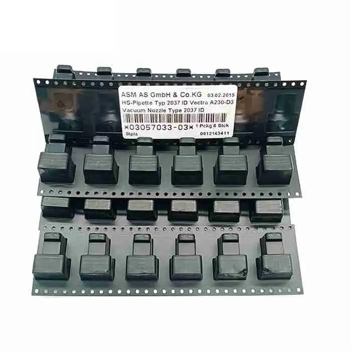
Correct small-component nozzles
Suitable low-force placement sleeves
Compatible SIPLACE SmartFeeder Xi units
Accurate feeder pickup-position calibration
Compatible machine and programming software
Stable component-tape pocket quality
Accurate solder-paste printing
Stable PCB support
Controlled factory temperature and humidity
When very small components are a critical purchasing requirement, request a representative pickup and placement test using the actual component size.
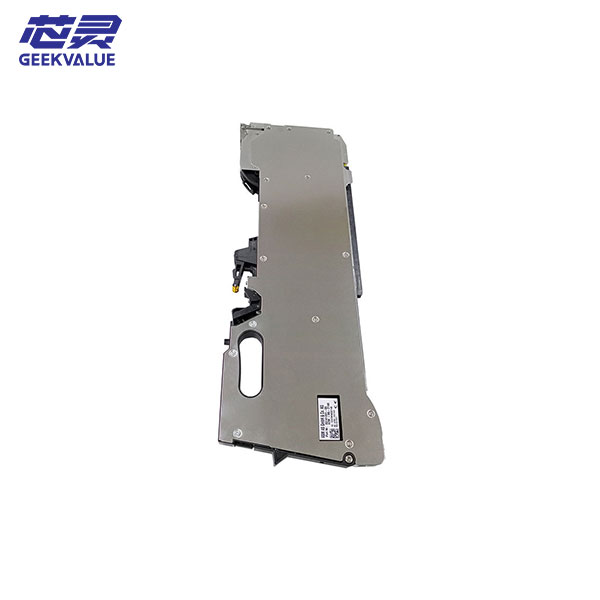
80 Feeder Positions and Component Supply
The SIPLACE TX2 supports up to 80 positions for standard 8 mm tape feeders. Wider tape feeders occupy multiple positions, so the actual number of physical feeders depends on the required tape-width combination.
Available Component-Supply Options
8 mm SIPLACE SmartFeeder Xi
12 mm and 16 mm tape feeders
24 mm, 32 mm and wider tape feeders
JEDEC trays
SIPLACE Tray Unit
Linear Dipping Unit
Glue Feeder
Force Verification Feeder
Application-specific component-supply systems
Information to Confirm With the Feeder Package
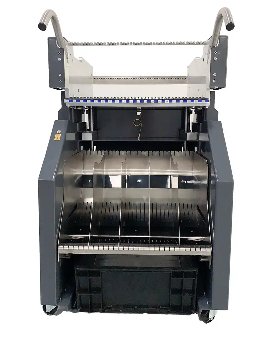
Number of feeder carts or tables supplied
Number of included 8 mm feeders
Required wider tape-feeder quantities
Feeder model and generation
Feeder firmware and machine compatibility
Feeder calibration status
Pickup and tape-indexing performance
Cart docking and communication condition
Reel holders and tape-waste containers
Required spare feeder quantity
Feeders, carts and tray systems are not automatically included with every used TX2. Every included item should be listed clearly in the quotation.
SIPLACE Tray Unit and Tray-Fed Components
A TX2 equipped with CPP or TWIN heads may be used for components supplied in JEDEC trays or wider carrier trays. The available tray system depends on the machine generation and installed component-supply package.
A suitable tray configuration can support:
Large integrated circuits
Power-semiconductor packages
Fine-pitch BGAs
Large processors and controllers
Specialized industrial components
Devices that cannot be supplied through tape feeders
Before ordering a machine for tray production, confirm:
Tray-unit model and part number
Supported tray dimensions
Number of storage levels
Tray elevator and transfer operation
Machine-software compatibility
Component pickup-position calibration
Required nozzles or grippers
Whether tray components can be refilled without stopping production
Single-Lane and Dual-Lane PCB Production
The SIPLACE TX2 may be configured with single-lane or dual-lane PCB transport. Conveyor configuration affects PCB width, line throughput and compatibility with the surrounding production equipment.
Standard PCB Length
Without the Long Board Option, the maximum supported PCB length is approximately 375 mm. Width depends on whether the machine operates in dual-lane or single-lane mode.
Single-Lane Configuration
With the applicable Long Board Option, single-lane operation can support PCBs from approximately 50 × 45 mm to 590 × 460 mm.
Dual-Lane Configuration
With the applicable Long Board Option, dual-lane production can support boards from approximately 50 × 45 mm to 590 × 260 mm per lane.
Dual-lane operation can reduce non-productive transport time by allowing another PCB to enter, wait or be processed while the opposite lane remains active.
PCB Information Required Before Selection
Minimum and maximum PCB length
Minimum and maximum PCB width
PCB thickness
Maximum assembled-board weight
Single-lane or dual-lane requirement
Same or different product on each lane
Required conveyor direction
Fixed conveyor-rail position
Production-line height
PCB edge-clearance requirement
Long Board Option requirement
Board support and warpage-control requirement
Interface with upstream and downstream equipment
Request actual conveyor photographs, measurements and a powered-on board-transport test before confirming PCB compatibility.
Placement Quality and Closed-Loop Process Control
The SIPLACE TX platform uses digital vision, sensors, linear drives and software-controlled correction to maintain placement stability at high speeds.
Depending on machine generation and installed options, available process-control functions may include:
Component-presence detection
Vacuum monitoring during pickup and placement
Component-position and rotation correction
Programmable placement-force monitoring
PCB fiducial recognition
PCB warpage measurement and compensation
Component-specific lighting
Component crack and chipping detection
Odd-shaped component recognition
PCB inspection functions
Barcode and QR-code reading
Bad-board and bad-panel recognition
Automatic setup verification
Production traceability
The presence of the TX2 model name does not prove that every optional camera, scanner, sensor or software function is installed. Required functions should be demonstrated on the individual machine.
Touchless and Low-Force Placement
The TX platform supports controlled placement forces as low as approximately 0.5 N with suitable head configurations. This can be useful for sensitive components, small packages and applications where excessive force could disturb solder paste or damage the part.
Placement force depends on the selected head:
CP20: approximately 0.5 N to 4.5 N
CPP: approximately 1 N to 15 N
TWIN: approximately 1 N to 30 N
Touchless or low-force placement still requires correct component definition, nozzle selection, PCB support, solder-paste process and machine calibration.
Typical SIPLACE TX2 Applications
The TX2 is suitable for factories that require compact line design, high placement output and the ability to configure the machine around the actual component mix.
Telecommunications and network equipment
Server and data-centre electronics
Automotive electronic modules
Industrial control boards
Consumer electronic products
Medical electronic assemblies
Power-management electronics
LED and display-control boards
High-volume EMS production
Mixed-component PCB assembly
Compact SMT line expansion
Replacement of an existing TX2 machine
A two-CP20 configuration is suitable for boards dominated by small tape-fed components. CP20 and CPP combinations provide broader mixed-component coverage, while CPP and TWIN configurations may be used for flexible end-of-line placement.
Using the TX2 in a Complete SMT Line
The TX2 can operate as a standalone placement module or as part of a line containing several TX machines with different head configurations.
A typical SMT line may include:
PCB loader
Solder paste printer
3D solder paste inspection system
SIPLACE TX2 high-speed placement machine
SIPLACE TX1, TX2 or another flexible placement module
Reflow oven
Automatic optical inspection system
PCB unloader
For example, one TX2 equipped with CP20 heads may place small components, while a second TX machine equipped with CPP or TWIN heads completes ICs, connectors and tray-fed components.
The total line output is determined by its slowest process. A high-speed TX2 will not increase overall throughput when the printer, flexible placement stage, reflow oven or inspection system remains the main bottleneck.
Used ASM SIPLACE TX2 Inspection Checklist
A used TX2 should be assessed as a complete placement system. External appearance and a successful startup do not confirm that the machine can maintain its specified output and placement quality.
1. Machine Identification
Complete machine model
TX2 or TX2i confirmation
Machine item number
Machine serial number
Manufacturing year
Total operating hours
Total placement counter
Original factory configuration
Current installed configuration
Station-software version
Programming-software compatibility
2. Placement-Head Identification
Head installed on gantry one
Head installed on gantry two
CP20, CPP or TWIN model confirmation
Head part and serial numbers
Individual operating hours
Individual placement counters
Installed component-camera type
Nozzle-changer configuration
Head maintenance and repair history
3. Gantry and Motion Inspection
Movement of both gantries
X-axis and Y-axis noise
Vibration during acceleration and deceleration
Machine homing and reference operation
Linear-motor condition
Encoder and position-feedback condition
Axis-drive alarm history
Cable-chain and trailing-cable condition
Gantry calibration and alignment
4. Placement-Head Inspection
Nozzle-segment or sleeve wear
Z-axis movement
Rotational-axis movement
Vacuum pressure and leakage
Component-sensor operation
Placement-force sensor operation
Nozzle-changer operation
Pickup and placement repeatability
Special nozzle or gripper operation
Head calibration status
5. Camera and Vision Inspection
Component camera on both gantries
High-resolution camera availability
PCB-camera image quality
Lighting-level operation
Component-shape recognition
Fiducial recognition
Pickup-position correction
PCB warpage measurement
Crack or chipping detection where installed
Camera calibration status
6. Conveyor Inspection
Single-lane or dual-lane conveyor
Synchronous and asynchronous operation where applicable
Automatic width adjustment
Conveyor belts and pulleys
PCB entrance and exit sensors
Board clamping and support
Long Board Option
Maximum measured PCB dimensions
Communication with surrounding equipment
7. Feeder and Component-Cart Inspection
Number of included component carts
Number and type of included feeders
Feeder tape-width combination
SmartFeeder or SmartFeeder Xi generation
Feeder firmware and software compatibility
Feeder pickup and indexing performance
Cart docking and locking condition
Communication-interface operation
Reel holders and waste-tape containers
Setup-verification functions
8. Tray and Special Component Supply
SIPLACE Tray Unit availability
JEDEC tray compatibility
Tray elevator and transfer operation
Linear Dipping Unit availability
Glue Feeder availability
Force Verification Feeder availability
Special nozzles and grippers
Pickup-position calibration
9. Included Equipment
Station computers and monitors
Machine-software backups
Product and configuration files
Nozzles and nozzle magazines
Feeder carts and feeders
Tray or special component-supply equipment
Transformer or voltage-conversion equipment
Operating and maintenance manuals
Calibration tools
Included spare parts
A complete inspection video should show machine startup, homing, both gantries, every installed head, feeder pickup, component recognition, nozzle changing, PCB transport and an actual sample placement program.
Common SIPLACE TX2 Maintenance Areas
The TX2 combines high acceleration, linear drives, precision cameras and fast placement heads. Preventive maintenance is necessary to maintain placement performance and process stability.
CP20 placement-head segments
CPP placement-head assemblies
TWIN Z-axis and rotational assemblies
Nozzle sleeves and nozzle holders
Nozzles and automatic nozzle changers
Vacuum valves, generators and filters
Placement-force and component sensors
Component cameras and lighting modules
PCB camera and fiducial lighting
Linear motors and encoders
Axis drives and control boards
Trailing cables and cable chains
Cooling fans and machine filters
Conveyor belts, pulleys and sensors
PCB support and warpage systems
Feeder-cart docking interfaces
SmartFeeder and SmartFeeder Xi units
Station computers and storage devices
Recommended maintenance includes placement-head cleaning, nozzle inspection, vacuum testing, camera calibration, feeder calibration, axis inspection, conveyor adjustment, filter replacement and verification of current software backups.
Who Should Consider a Used SIPLACE TX2?
A used TX2 may be suitable for manufacturers that require compact high-output placement capacity or need to expand or replace equipment in an existing TX-based production line.
The machine may be a practical option when:
The factory has limited production-line space
Two placement gantries provide the required output
The PCB contains a high quantity of small components
The product also requires flexible IC placement
The factory already owns compatible SIPLACE feeders
The existing line includes TX1, TX2 or TX2i machines
Existing technicians understand SIPLACE TX operation
Replacement heads and spare parts are available
A damaged TX2 must be replaced without redesigning the line
A used-machine investment is preferred over a new platform
A newer machine or different TX configuration may be more suitable when the project requires specific automation functions, precision packages, software integration or production capabilities not included with the available used equipment.
Information Required for a SIPLACE TX2 Quotation
TX2 or TX2i model requirement
Required machine quantity
Preferred manufacturing year
Preferred machine condition
Required CP20, CPP or TWIN head combination
Target production output
Minimum component package
Maximum component dimensions
Maximum component height and weight
Required placement accuracy
Required placement force
PCB dimensions and thickness
Single-lane or dual-lane requirement
Long Board Option requirement
Required feeder quantities and tape widths
Tray or special component-supply requirement
Existing SIPLACE machines and feeders
Factory voltage and frequency
Compressed-air availability
Destination country
Required delivery schedule
Customers who need a cycle-time assessment may send the PCB BOM, placement file, component list, panel dimensions and target hourly output for preliminary machine matching.
Frequently Asked Questions
What is the ASM SIPLACE TX2 used for?
The SIPLACE TX2 is a compact dual-gantry placement machine used for high-output small-component placement and flexible processing of ICs, trays and selected odd-shaped components.
What is the placement speed of the SIPLACE TX2?
The published benchmark placement speed of the standard SIPLACE TX2 is up to approximately 85,500 components per hour.
Can the SIPLACE TX2 produce 96,000 CPH?
The 96,000 CPH benchmark rating belongs to the SIPLACE TX2i. The standard TX2 is rated at up to approximately 85,500 CPH.
How many placement heads does the TX2 have?
The TX2 is a dual-gantry configuration with two placement-head positions. The exact heads installed on the machine must be confirmed individually.
Which placement heads can be installed on the TX2?
Common TX platform options include the CP20 high-speed head, CPP flexible head and TWIN head for larger or odd-shaped components.
What is the component range of the SIPLACE TX2?
The complete platform spectrum extends from approximately 0.12 × 0.12 mm to selected components around 200 × 110 mm. The actual range depends on the two installed heads.
What placement accuracy does the TX2 provide?
Accuracy depends on the placement head. Published values are approximately 25 μm for CP20, 34 μm for CPP and 22 μm for TWIN at 3 sigma.
How many feeders can be installed?
The SIPLACE TX2 supports up to 80 positions for standard 8 mm tape feeders. Wider tape feeders occupy multiple positions and reduce the total feeder quantity.
Does the TX2 support tray-fed components?
Yes. Depending on its configuration, the TX2 can use JEDEC trays or the SIPLACE Tray Unit with suitable CPP or TWIN heads.
Does the TX2 support dual-lane production?
Yes. The TX platform supports dual-lane PCB transport. With the Long Board Option, PCB length can reach approximately 590 mm.
What PCB size can the TX2 process?
With the applicable Long Board Option, the machine can process boards up to approximately 590 × 460 mm in single-lane mode or 590 × 260 mm per lane in dual-lane mode.
What is the difference between TX1, TX2 and TX2i?
TX1 is the lower-output single-head configuration, TX2 is the standard dual-head configuration rated at up to 85,500 CPH, and TX2i is the highest-output configuration rated at up to 96,000 CPH.
Are feeders included with a used TX2?
Not automatically. Feeders, component carts, tray systems, nozzles and spare parts may be included or quoted separately. Every included item should be stated clearly in the quotation.
What should be tested before purchasing a used TX2?
Test both gantries, every installed placement head, component cameras, PCB camera, vacuum and force sensors, nozzle changers, conveyor, feeders, component carts, station computers and required software functions.
Request ASM SIPLACE TX2 Availability
Send your required placement-head combination, PCB dimensions, component range, target output, feeder requirement, conveyor configuration and destination country. GEEKVALUE will check available ASM SIPLACE TX2 machines and confirm the model, serial number, manufacturing year, installed heads, conveyor, software, included accessories, inspection scope and delivery arrangement.
View the complete ASM SIPLACE TX Series placement machine range, or explore compatible SIPLACE SMT feeders, placement heads and SMT nozzles.