The ASM SIPLACE CA4 is a chip assembly platform developed for direct placement of bare dies from wafers and conventional feeder-based SMD placement. Depending on its configuration, the machine can be used for flip chip, die attach, SMD-only production or
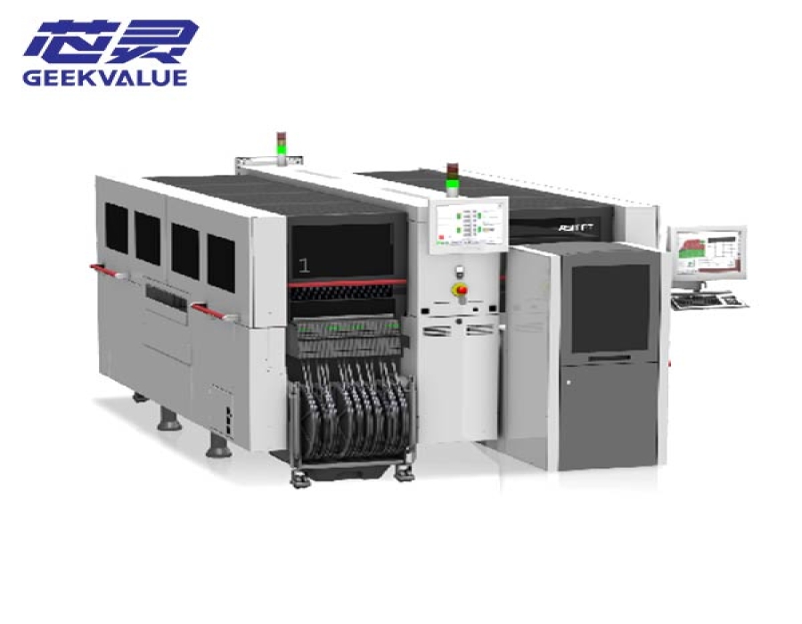
The ASM SIPLACE CA4 is a chip assembly platform developed for direct placement of bare dies from wafers and conventional feeder-based SMD placement. Depending on its configuration, the machine can be used for flip chip, die attach, SMD-only production or a mixed process that places dies and standard components in a single production flow.
CA4 machines may differ in wafer systems, feeder changeover tables, placement heads, conveyor design and process modules. The exact model version, installed configuration, machine condition, included accessories, price and delivery time should therefore be confirmed before quotation.
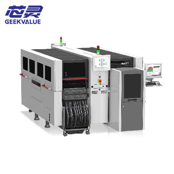
The SIPLACE CA platform combines semiconductor chip assembly with the placement functions of the SIPLACE X-series platform. Bare dies can be supplied directly from wafers, while conventional components can be supplied from feeder changeover tables.
| Process | Component Supply | Reference Throughput | Reference Accuracy | Die or Component Range |
|---|---|---|---|---|
| Flip Chip | SIPLACE Wafer System | Up to 46,000 components per hour with four wafer systems | ±10 µm at 3σ with wafer-lane conveyor; ±12 µm at 3σ with panel-lane conveyor | 0.5 mm to 15 mm |
| Die Attach | SIPLACE Wafer System | Up to 30,000 components per hour with four wafer systems | ±10 µm at 3σ with wafer-lane conveyor; ±12 µm at 3σ with panel-lane conveyor | 0.8 mm to 15 mm; smaller dies may require further evaluation |
| SMD Placement | Feeder changeover tables | Up to 126,500 components per hour with four changeover tables | ±15 µm at 3σ | 0.11 mm to 15 mm |
The listed throughput values are ASMPT benchmark figures for specified platform configurations. They are not guaranteed production rates. Actual output depends on the installed equipment, component mix, wafer or feeder arrangement, substrate layout, process settings and machine condition.
The SIPLACE Wafer System supplies bare dies directly to the placement machine. It uses a horizontal wafer arrangement and supports automatic wafer exchange, wafer-map processing, hoop-ring handling and production involving more than one die type.
| Supported Wafer Sizes | 4 to 12 inches |
|---|---|
| Wafer Stretcher | 8-inch and 12-inch; 4-inch and 6-inch configurations may require confirmation |
| Minimum Silicon Die Thickness | 50 µm |
| Flip-Chip Die Size | 0.5 mm to 15 mm |
| Minimum Bump Size | 25 µm |
| Minimum Bump Pitch | 50 µm |
| Wafer Stretch Range | 2 mm to 8 mm |
| Die Ejection | Programmable eject speed |
The platform also supports low-force handling for sensitive dies. Depending on the installed placement head and process setup, pickup and placement can be performed without contact pressure, while programmable placement force ranges from 0.5 N to 15 N.
A SIPLACE Linear Dipping Unit can be used to apply flux before die placement. The system allows the application speed and dwell time to be programmed for the production process.
| Dipping System | Linear Dipping Unit LDU 2 X |
|---|---|
| Supported Flux Viscosity | 3,000 to 100,000 cps |
| Flux Height Accuracy | ±5 µm |
| Flux Refill Monitoring | Available as an optional function |
| Process Settings | Programmable application speed and dwell time |
The SIPLACE CA platform can exchange wafer systems and feeder changeover tables. ASMPT documentation describes configurations in which the combined number of wafer systems and changeover tables equals four. This allows the machine to be arranged for wafer-based assembly, feeder-based SMD placement or a combination of both.
| Example Arrangement | Wafer Systems | Feeder Changeover Tables | Production Focus |
|---|---|---|---|
| Wafer-focused configuration | 4 | 0 | Flip-chip or die-attach production directly from wafers |
| Mixed configuration | 2 | 2 | Combined bare-die and feeder-based SMD placement |
| Feeder-focused configuration | 0 | 4 | Conventional SMD placement |
These examples describe the platform concept rather than the configuration of a specific available machine. The number of wafer systems, changeover tables and installed process modules must be checked individually.
Different conveyor arrangements allow the SIPLACE CA4 to process conventional PCBs, ceramic substrates, flexible materials, carriers, wafers and larger panels. The supported format depends on the conveyor fitted to the machine.
| Substrate Types | FR4, ceramics, flex materials, boats, 8-inch and 12-inch wafers, and other application-specific substrates |
|---|---|
| Substrate Thickness | 0.3 mm to 4.5 mm |
| Reference Substrate Range | 50 × 50 mm to 685 × 650 mm, depending on conveyor type |
| Conveyor Options | Flexible dual conveyor, single-lane conveyor, wafer-lane conveyor and panel-lane conveyor |
| Transport Modes | Synchronous or asynchronous, depending on conveyor configuration |
The SIPLACE CA4 is intended for production where direct wafer-fed die placement must be integrated with conventional SMT assembly. Typical process requirements include flip-chip assembly, direct die attach, system-in-package production, wafer- or panel-level packaging and assemblies that combine bare dies with passive or packaged SMD components.
The machine may also be configured for feeder-based SMD production without wafer processing. For mixed applications, the required balance between wafer systems and feeder changeover tables should be determined from the number of die types, SMD component range, product changeover requirements and expected production volume.
| Item | Why It Matters |
|---|---|
| Exact Model and Version | Machine documentation may identify the equipment as SIPLACE CA, CA4 or CA4 V2, depending on its generation and configuration. |
| Required Process | Flip chip, die attach, SMD placement and mixed production require different equipment arrangements. |
| Wafer-System Quantity | Determines wafer capacity, die variety and the reference throughput available for wafer-fed production. |
| Feeder Changeover Tables | Determines the amount of feeder-based component supply available for SMD placement. |
| Placement Heads and Process Modules | Affect component range, placement force, accuracy and supported assembly processes. |
| Wafer and Die Requirements | Wafer diameter, die thickness, die size, bump diameter and bump pitch should be checked against the installed wafer equipment. |
| Conveyor Configuration | Determines the supported substrate format and compatibility with the production line. |
| Flux Dipping Equipment | The Linear Dipping Unit and its supporting options may not be installed on every machine. |
| Software and Wafer-Map Functions | Software version and available licenses should match the intended process and existing production environment. |
| Machine Condition and Delivery Scope | Actual photos, included accessories, equipment condition and supporting systems should be listed in the final quotation. |
GEEKVALUE provides sourcing and quotation support for ASM SIPLACE CA4 chip assembly machines according to current availability. Available equipment may differ in model version, wafer configuration, feeder setup, conveyor type, software, condition and included process modules.
For equipment matching, send us the required assembly process, wafer diameter, die dimensions, substrate size, production requirements and destination country. We will confirm available machine information, configuration, photos, quotation scope, price and estimated delivery time before an order is placed.
Yes, when it has the required wafer systems, feeder changeover tables, placement heads and process modules. It may also be configured only for wafer-based chip assembly or only for feeder-based SMD placement.
No. The platform allows wafer systems and feeder changeover tables to be combined, with the total number described in the platform documentation being four. The exact arrangement must be checked on the available machine.
No. The values are reference benchmark rates for defined four-system configurations. Actual production speed changes with the process, die and component mix, product layout, supply arrangement, program settings and condition of the equipment.
Not necessarily. The dipping unit, flux monitoring functions, wafer stretchers, hoop-ring equipment and other process accessories depend on the installed configuration and quotation scope.
Provide the intended process, wafer size, die and bump dimensions, substrate format, required SMD components, production target and delivery destination. When the exact configuration is unknown, send the available product and process information for further evaluation.
If you are not sure whether this product matches your machine, send us the model, label photo or old part picture for checking.