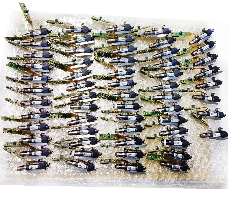
Used ASM SIPLACE HS60 mounter with four 12-nozzle heads, 60,000 CPH output and up to 144 feeder tracks.
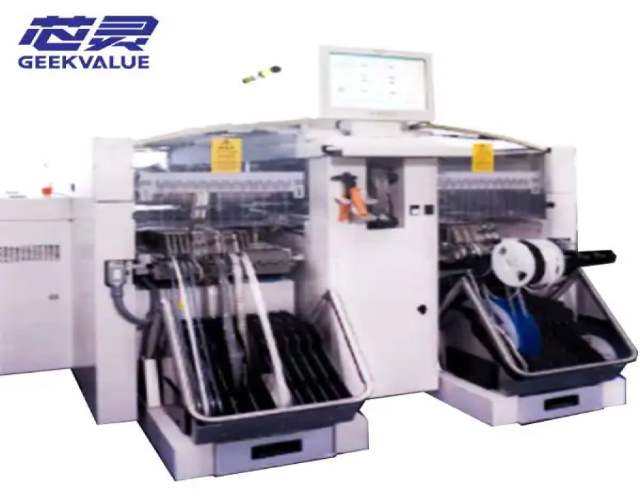
The ASM SIPLACE HS60 SMT pick and place machine is a high-speed chip-placement system designed for volume PCB assembly involving large quantities of small and medium-sized SMD components. Equipped with four gantries and four 12-nozzle Collect & Place heads, the HS60 delivers a benchmark placement rate of up to 60,000 components per hour.
GEEKVALUE supplies available used ASM and Siemens SIPLACE HS60 machines according to the required conveyor configuration, placement-head condition, feeder package, software generation and destination country. Because the HS60 is a legacy SIPLACE platform, the machine serial number, manufacturing year, operating hours and installed options should be confirmed before quotation.
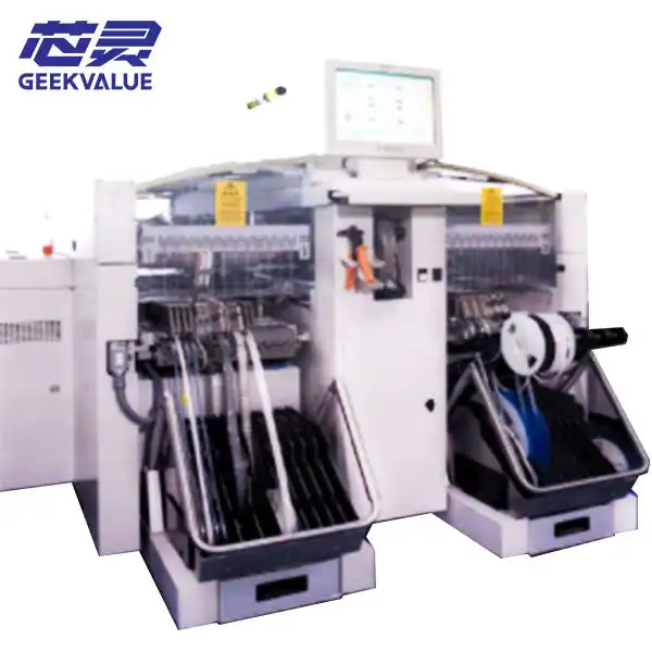
The SIPLACE HS60 was developed as a dedicated high-speed placement module for SMT production lines. Its main role is the rapid placement of resistors, capacitors, small IC packages and other tape-fed SMD components before larger or more complex components are placed by a flexible mounter.
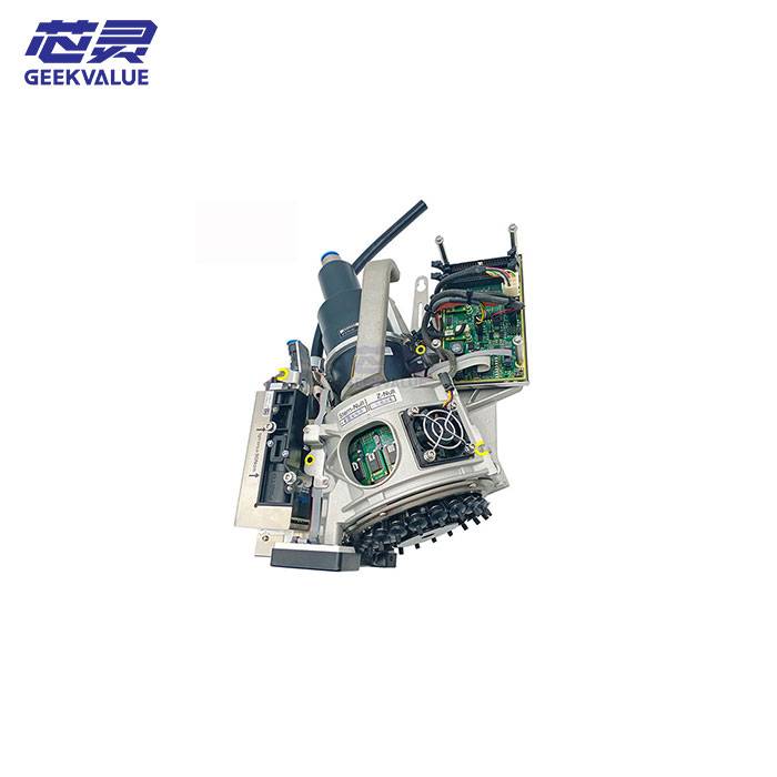
The machine uses four independently operating gantries. Each gantry is normally equipped with a star-shaped 12-nozzle Collect & Place head, allowing multiple components to be collected, optically inspected, rotated and placed during each operating cycle.
Benchmark placement speed of up to 60,000 CPH
Four independent X-Y gantries
Four 12-nozzle Collect & Place heads
Component range from 0.6 × 0.3 mm to 18.7 × 18.7 mm
Up to 144 tracks for 8 mm tape feeders
Single-lane and dual-lane conveyor configurations
Automatic component vision and PCB position recognition
Suitable for high-volume small-component placement
| Specification | ASM SIPLACE HS60 |
|---|---|
| Machine type | High-speed SMT chip mounter |
| Placement-head type | 12-nozzle Collect & Place head |
| Number of gantries | 4 |
| Total placement heads | 4 × 12-nozzle heads |
| Benchmark placement rate | Up to 60,000 CPH |
| Component range | 0.6 × 0.3 mm to 18.7 × 18.7 mm |
| Maximum placement accuracy | Approximately 80/75 μm at 4 sigma, depending on specification |
| Minimum PCB size | Approximately 50 × 50 mm |
| Single-lane PCB size | Up to approximately 368 × 460 mm |
| Dual-lane PCB size | Up to approximately 368 × 216 mm per lane |
| Feeder capacity | Up to 144 tracks for 8 mm tape feeders |
| Component tables | Up to four quick-change feeder tables |
| Feeder types | Tape, bulk-case, stick and application-specific feeders |
| Operating environment | Legacy SIPLACE Windows and RMOS system, depending on configuration |
| Typical application | High-volume placement of small and medium SMD components |
Configuration notice: The specifications above describe common SIPLACE HS60 configurations. PCB capacity, conveyor format, software version, feeder compatibility and installed options can differ between individual machines. Final matching must be based on the actual machine label and inspection results.
The HS60 achieves its output through four separately controlled placement gantries. Instead of relying on one placement head to complete every component position, the production program distributes the placement work across the four gantries.
This arrangement helps reduce travel distance and allows several placement sequences to be carried out within the same machine. When the component list and feeder arrangement are properly balanced, the four-gantry design provides efficient high-volume placement.
The real output of the machine depends on more than its benchmark rating. Factors affecting production speed include:
Number of placements on each PCB
Distribution of components between the four gantries
Feeder positions and tape widths
PCB dimensions and panel format
Component inspection and rotation requirements
Conveyor loading and unloading time
Nozzle configuration and component pickup stability
Production-program optimization
For this reason, 60,000 CPH should be treated as a benchmark specification rather than a guaranteed output for every PCB program.
Each HS60 placement head contains twelve nozzle positions arranged around a rotating star. During the collection sequence, multiple components are picked from the feeder table. The components are then inspected by the vision system, rotated to their programmed angles and placed onto the PCB.
The Collect & Place principle provides several advantages for high-speed production:
Multiple components can be collected during one operating sequence
Component position and rotation can be checked before placement
Pickup offsets can be corrected by the machine vision system
Incorrect or missing components can be detected
The rotating-head structure supports consistent cycle times
Small components can be processed with lower travel distances
Because all four gantries use this placement principle, the condition of every head is important. Uneven head performance, worn sleeves, vacuum instability or camera problems can reduce the output of the entire machine.
The standard 12-nozzle HS60 head handles components from approximately 0.6 × 0.3 mm, commonly associated with 0201-inch components, up to 18.7 × 18.7 mm.
The machine is therefore best suited to products with a large quantity of small and medium tape-fed components, including:
Chip resistors
Multilayer ceramic capacitors
Small diodes and transistors
SOT and small-outline packages
Small IC packages
Selected QFP, BGA and CSP packages within the supported size range
LED and communication-board components
Other standard surface-mount components
The HS60 is not normally selected as the only placement machine when a PCB contains large connectors, tall components, heavy devices or complex odd-shaped parts. In these applications, it is commonly combined with a flexible SIPLACE placement machine.
Different SIPLACE HS60 machines may be equipped with single-lane or dual-lane PCB transport. The correct conveyor version should be selected according to PCB width, production volume and the configuration of the other equipment in the SMT line.
A common single-lane configuration supports PCB sizes from approximately 50 × 50 mm to 368 × 460 mm. This format is suitable for wider boards, panels and production lines that process one PCB at a time.
A dual-lane configuration can process two narrower PCB streams, with a common maximum width of approximately 216 mm per lane. Dual-lane production can reduce waiting time between boards and improve line utilization when the upstream and downstream equipment supports compatible dual-lane operation.
Before ordering a machine, confirm:
Required PCB length and width
PCB thickness
Panel weight
Single-lane or dual-lane requirement
Fixed-rail position
Conveyor direction
Line height
SMEMA interface requirements
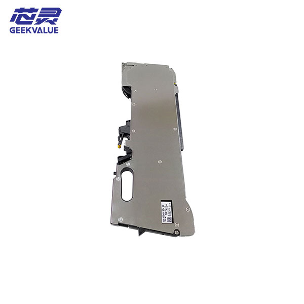
The SIPLACE HS60 can support up to 144 tracks for 8 mm tape feeders when configured with four feeder tables. This large feeder capacity allows the machine to process PCBs containing many small-component part numbers without excessive feeder changes.
Wider feeders occupy more track positions. A 12 mm, 16 mm, 24 mm or wider feeder will reduce the total number of feeder units that can be installed at the same time.
The feeder package should therefore be calculated according to the actual BOM rather than only the maximum 144-track specification.
Number of feeder tables included
Number of 8 mm feeders
Required wider feeder quantities
Feeder generation and machine compatibility
Feeder-table wheel and locking condition
Reel holders and waste-tape containers
Feeder calibration and maintenance status
Spare feeder requirement
Feeders are not automatically included with every used HS60 quotation. The commercial offer should list the machine, tables, feeders, nozzles and other accessories separately.
The same machine may be described in the used-equipment market as an ASM SIPLACE HS60, Siemens SIPLACE HS60, Siemens Dematic HS60 or simply SIPLACE HS-60.
Many original machines were manufactured during the Siemens or Siemens Dematic period, so the physical machine nameplate may not display the newer ASM brand name. Customers should identify the equipment by its complete SIPLACE model, serial number, year and installed hardware instead of relying only on the brand wording used in a sales listing.
The HS60 is primarily a high-speed chip-placement machine. A typical production line may use the HS60 near the beginning of the placement section to install small components, followed by a flexible mounter for larger ICs, connectors and special components.
Depending on the factory’s installed equipment, the HS60 may be combined with legacy SIPLACE machines such as:
SIPLACE F5 HM
SIPLACE HF
SIPLACE S-27 HM
Other compatible SIPLACE high-flexibility platforms
The complete line should be balanced according to the number of small-component placements and the number of flexible-component placements. Installing a high-speed HS60 does not automatically increase total line output if the following machine becomes the production bottleneck.
Because the HS60 is a legacy machine, condition assessment is more important than the model name alone. Two machines with the same year can have very different operating hours, maintenance history and head condition.
Complete machine model
Serial number
Manufacturing year
Total operating hours
Total placement counter
Software and station-computer version
Single-lane or dual-lane conveyor
Movement of all four gantries
Axis noise and vibration
Motor, encoder and drive status
Flat ribbon cable condition
Energy-chain and pneumatic-hose condition
Machine homing and reference accuracy
Condition of all four 12-nozzle heads
Head placement counters
Nozzle sleeve wear
Star rotation stability
Vacuum pressure and leakage
Z-axis and rotational-axis movement
Component-camera image quality
Pickup and placement test results
Conveyor width adjustment
Belt and rail condition
PCB clamping and support
Board sensors
Entrance and exit signals
Compatibility with surrounding line equipment
Number of feeder tables
Included feeders and tape widths
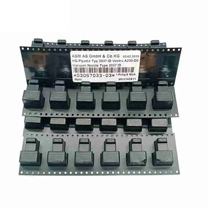
Nozzle quantity and nozzle types
Station computer and monitor
Software backup
Machine manuals
Transformer and electrical accessories
Available spare parts
A powered-on operating video should demonstrate all four gantries, head rotation, feeder pickup, component recognition, conveyor operation and alarm status. External photographs alone are not sufficient to evaluate a used HS60.
Long-term HS60 operation depends on preventive maintenance and the availability of suitable replacement parts. Parts that should be checked during machine inspection include:
Placement-head sleeves and nozzle holders
Nozzles and nozzle changers
Vacuum valves and pneumatic components
Component cameras and lighting modules
PCB cameras and sensors
Gantry motors and encoders
Flat ribbon cables
Axis drives and control boards
Conveyor belts and rail components
Station computer and communication hardware
GEEKVALUE supports legacy SIPLACE production with machine inspection, placement heads, feeders, nozzles, motors, boards, cables and other replacement components according to machine model and part number.
A used HS60 may be suitable for manufacturers that already operate compatible legacy SIPLACE equipment and need additional high-speed placement capacity without replacing the complete SMT line.
The machine is particularly relevant when:
The PCB contains a high number of small SMD placements
The factory already has compatible SIPLACE feeders
Existing technicians understand legacy SIPLACE systems
Replacement parts and repair support are available
The production line requires additional chip-placement capacity
The equipment budget does not support a newer placement platform
A newer placement platform may be more suitable when the project requires very small metric components, higher accuracy, lower energy use, modern factory software integration or long-term manufacturer support.
Provide the following information so that the correct machine and accessory package can be checked:
Required machine quantity
Preferred manufacturing year
Single-lane or dual-lane conveyor
Maximum PCB dimensions
Smallest and largest component
Target line output
Required feeder quantities
Required feeder tape widths
Need for nozzles and feeder tables
Current SIPLACE machine models
Factory voltage
Destination country
Required shipment date
Customers who are unsure whether the HS60 is suitable may send a PCB BOM, placement file, board dimensions and target cycle time for preliminary production matching.
The SIPLACE HS60 has a benchmark placement rate of up to 60,000 components per hour. Actual output depends on the PCB program, feeder arrangement, component distribution, conveyor timing and machine condition.
A standard HS60 configuration has four gantries and four 12-nozzle Collect & Place heads, providing a total of 48 nozzle positions across the machine.
The standard component range is approximately 0.6 × 0.3 mm to 18.7 × 18.7 mm. The exact supported package also depends on nozzle type, component height, vision settings and machine software.
The machine can support up to 144 tracks for 8 mm tape feeders with the appropriate four-table configuration. Wider feeders occupy additional tracks and reduce the total installed feeder quantity.
Yes. HS60 machines may be configured with single-lane or dual-lane conveyor systems. The installed conveyor must be checked on the actual machine because it cannot be confirmed from the model name alone.
The HS60 is primarily designed for small and medium components up to approximately 18.7 × 18.7 mm. Large connectors, tall devices and odd-shaped components are normally assigned to a flexible placement machine.
Listings may use Siemens, Siemens Dematic or ASM wording for this legacy SIPLACE model. The actual machine should be identified through its SIPLACE HS60 nameplate, serial number and installed configuration.
Test all four gantries, all four placement heads, component cameras, PCB camera, vacuum system, conveyor, feeder interfaces, station computer and software communication. A powered-on placement test is strongly recommended.
Contact GEEKVALUE with your required conveyor configuration, PCB dimensions, component range, feeder quantity, destination country and target production output. We will check available SIPLACE HS60 machines and confirm the machine condition, serial information, included accessories, inspection scope and delivery arrangement.
Explore more ASM SIPLACE SMT placement machines, compatible SIPLACE SMT feeders, placement heads and SMT nozzles.
If you are not sure whether this product matches your machine, send us the model, label photo or old part picture for checking.