)










SMT machine troubleshooting should begin with the symptom, production conditions and affected system—not with an assumed failed part. A feeding, pickup, recognition, placement, motion or PCB-transfer problem may involve material, setup, sensors, mechanical conditions, control feedback or a damaged component.
A practical troubleshooting path is:
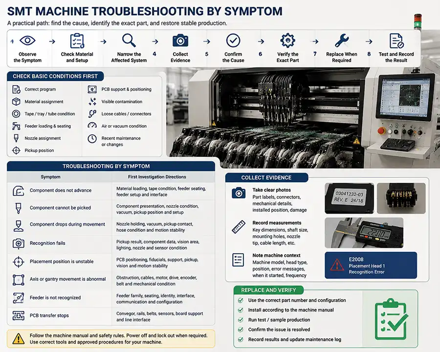
Observe the Symptom → Check Material and Setup → Narrow the Affected System → Collect Evidence → Confirm the Cause → Verify the Exact Part → Replace When Required → Test and Record the Result
Exact service procedures, guarded-area access and machine-specific adjustments should follow the documentation and authorization required for the installed equipment.
Check Basic Conditions Before Replacing SMT Machine Parts
Before focusing on one feeder, nozzle, motor or sensor, confirm the production conditions that may create an apparent hardware fault.
Correct production program
Correct component and material assignment
Tape, tray or tube condition
Feeder loading and seating
Nozzle assignment
Pickup position
PCB support and positioning
Visible contamination
Loose cables or connectors
Air or vacuum condition
Recent maintenance, service or setup changes
Also determine whether the symptom follows the material, feeder, nozzle, head position, axis or machine area; whether it affects one product or several products; and whether it began after a setup, maintenance or software change.
SMT Machine Troubleshooting by Symptom
| Symptom | First Investigation Directions |
|---|---|
| Component does not advance | Material loading, tape condition, feeder seating, feeder setup and interface |
| Component cannot be picked | Component presentation, nozzle condition, vacuum, pickup position and setup |
| Component drops during movement | Nozzle holding, vacuum, pickup contact, hose condition and motion stability |
| Recognition fails | Pickup result, component data, vision area, lighting, nozzle and sensor condition |
| Placement position is unstable | PCB positioning, fiducials, support, pickup, vision and motion stability |
| Axis or gantry movement is abnormal | Obstruction, cables, motor, drive, encoder, belt and mechanical condition |
| Feeder is not recognized | Feeder family, seating, identity, interface, communication and configuration |
| PCB transfer stops | Conveyor, rails, belts, sensors, board support and line interface |
Use the table to choose an investigation direction. The confirmed cause should come from repeated evidence, inspection and the exact machine documentation.
Components Do Not Advance or Present Correctly
When a component does not reach the expected pickup position, begin with the material-presentation and feeder system.
Check the material assignment, tape loading, carrier tape, cover tape, component pockets, feeder seating, interface cleanliness and visible mechanical condition. Record whether the problem follows the material, the feeder or one machine position.
Packaging, loading, setup, sensor feedback and communication may all affect presentation. If the symptom consistently follows the same feeder and inspection confirms mechanical or interface damage, review the relevant SMT feeder or feeder-related part using the exact feeder family and machine platform.
The Machine Cannot Pick Up the Component
A pickup failure may involve both component presentation and the pickup system. Confirm that the component reaches the correct pickup position before evaluating the nozzle.
Inspect the nozzle tip for visible contamination, wear or damage.
Confirm that the assigned nozzle type suits the component.
Review visible vacuum, hose and connector conditions.
Determine whether the problem follows the nozzle, feeder, component or head position.
Compare consistent and intermittent pickup behavior under the same setup.
If the issue follows the same pickup tool and its condition is confirmed, review available SMT nozzles and verify the nozzle code, head interface and machine configuration before replacement.
The Component Drops During Movement
This symptom occurs after pickup, when the component is not held reliably during movement.
Inspect the pickup tool, visible vacuum path, hose condition and pickup contact. Check whether the component was centered and securely held, whether the symptom follows one nozzle or head position and whether unusual movement or vibration is present.
The investigation should focus on holding condition and motion stability rather than repeating the complete pickup-failure process. A component drop does not automatically mean the nozzle must be replaced.
Vision or Component Recognition Fails
Recognition failure may begin with the pickup result, component data, optical condition or a feedback-system problem.
Confirm that the component is present after pickup.
Review whether the pickup result is centered and stable.
Check approved external camera and lighting areas for contamination.
Confirm the component and production-program data.
Determine whether the issue is product-specific, component-specific or position-specific.
Inspect accessible sensor, cable and connector areas.
Vision measures the component or PCB condition, control software interprets and uses the measurement, and motion systems execute the resulting movement.
If inspection confirms damage to a camera-related part, lighting component, sensor, cable or connector, verify the exact item before reviewing available SMT machine parts.
Placement Position Is Unstable
Placement instability may involve PCB positioning, fiducial recognition, board support, pickup offset, nozzle or head condition, vision measurement, conveyor clamping, program data or motion stability.
First determine whether the problem affects one component or the complete PCB. Then check whether it follows one nozzle, head position, board location or product. Review PCB support, visible fiducial condition and repeated patterns in previous production records.
Placement instability is not automatically proof of a placement-head failure. Machine-specific alignment or calibration should follow the applicable machine documentation or qualified service procedure.
Axis, Gantry or Head Movement Is Abnormal
Abnormal movement may involve a mechanical obstruction, motor, drive, encoder, belt, coupling, cable, connector, guide, bearing or recent service change.
Record the affected axis or position, check for visible obstruction and inspect approved external cable and connector areas. Compare abnormal sound, vibration, interrupted movement or repeated position alarms with maintenance history.
Stop production and follow the required machine procedure when movement may damage the machine, tooling, PCB or components.
When inspection or qualified service evidence confirms a motor, encoder, belt, cable or related motion component, verify the exact item before reviewing available SMT motor or motion-system replacements.
The Machine Does Not Recognize a Feeder
A feeder-recognition problem concerns identity, seating, interface, communication or compatibility rather than physical component advance.
Confirm the feeder family, machine model and generation. Reseat the feeder according to the applicable procedure, inspect visible contacts and determine whether the symptom follows the feeder or remains at one machine position. Also review recent setup, software or configuration changes.
This evidence helps separate feeder hardware condition from identification, interface and machine-configuration issues. A communication symptom does not automatically require feeder replacement.
PCB Transfer or Conveyor Operation Is Interrupted
PCB-transfer interruptions may involve obstructions, belt wear, rail or width settings, sensors, stops, clamps, board support, PCB format or connected upstream and downstream equipment.
Check where the board stops, whether the symptom follows one PCB type and whether an interface condition exists between machines. Inspect accessible belt, rail and sensor areas and confirm the relevant line settings.
The conveyor transports and supports the PCB, sensors provide presence or position feedback, and control systems coordinate transfer.
Confirm the Cause Before Replacing a Part
Replacement should follow evidence such as:
A repeated and reproducible symptom
Visible damage or verified wear
A problem that consistently follows the same part
Comparison with maintenance history
Approved testing or service evidence
Machine documentation
Qualified technician confirmation
Reproduce the Symptom → Narrow the System → Confirm the Cause → Identify the Exact Part → Replace When Required → Test the Result
Use a structured process to identify the correct SMT machine part before ordering or installing a replacement. Confirm the exact machine model, complete part number, suffix, connector, mounting arrangement and installed configuration rather than relying on appearance alone.
Do not use unverified electrical or control parts between machines as a compatibility test.
Use Verified Replacements for Production Recovery
After the affected system and replacement need have been confirmed, check whether a suitable verified spare is already available. A physically present part may still delay recovery if its revision, connector, mounting arrangement or machine compatibility is incorrect.
Selected spares may be practical for parts that are production-critical, used across several machines, associated with recurring maintenance history or difficult to obtain quickly.
Keeping more than one verified spare may also be practical when the same part is used across several critical machines, consumed repeatedly or difficult to obtain within the required production-recovery time.
The quantity should reflect machine coverage, usage history, supplier lead time and downtime risk rather than a general recommendation to stock multiple units of every part.
Use the confirmed machine and part information when reviewing available ASM/SIPLACE SMT machine parts.
Repeated troubleshooting results should also feed into the factory's SMT machine preventive maintenance and critical spare-parts planning process.
Record the Troubleshooting Result
Record enough information to support future troubleshooting and preventive maintenance:
Date
Machine and production-line position
Product being assembled
Observed symptom
Initial checks completed
Affected or suspected system
Confirmed cause
Part number when applicable
Action or replacement used
Test result
Production-recovery time
Whether spare stock should be replenished
Technician notes
Repeated records can reveal recurring symptoms, frequently used replacements and conditions that should be addressed through maintenance or spare-parts planning. When a verified spare is used, review whether the remaining stock is sufficient for the machines and production lines it supports.
When to Stop and Request Technical Support
Stop normal troubleshooting and follow the machine’s approved procedure when:
Movement is unsafe or uncontrolled.
An electrical burning smell or visible electrical damage is present.
Protective stops repeat.
Internal wiring appears damaged.
Severe mechanical interference occurs.
The issue requires guarded-area access.
Unconfirmed parameter or software changes would be required.
Safe operation is uncertain.
The problem remains after approved initial checks.
Information to Prepare for WhatsApp Review
Prepare the machine model and generation, exact configuration, product being assembled, symptom description, alarm text when available, when the problem began, checks already completed and whether the symptom follows one feeder, nozzle, head position, axis or product.
Also include the complete part number and suffix when known, clear machine-area and label photos, connector or mounting details, required quantity and whether a verified spare is already available.
Send the prepared information through WhatsApp for review of the likely affected system and replacement requirement. Complete evidence allows a more useful review than one image or alarm code alone.
Confirm the Fault and Prepare the Correct SMT Replacement Part
Observed Symptom → Initial Checks → Likely System → Confirmed Cause → Exact Part Verification → Available Replacement
Use the troubleshooting result to determine whether a replacement is required, then verify the exact part against the installed machine before reviewing available ASM/SIPLACE replacement options.
Contact us through WhatsApp with the machine model, symptom, alarm information, completed checks, part number and clear photos when you need help reviewing the likely replacement direction or planning suitable verified spare quantities.
Frequently Asked Questions About SMT Machine Troubleshooting
What should be checked first when an SMT machine stops?
Check the production program, material assignment, feeder loading, nozzle assignment, pickup position, vacuum condition, visible contamination, connectors and whether the symptom follows one product, part or machine position.
Does a feeder alarm always mean the feeder is faulty?
No. Check tape loading, packaging, feeder seating, setup, interface condition, communication and machine configuration before deciding whether feeder replacement is required.
What causes an SMT machine to miss a component pickup?
Possible investigation areas include component presentation, nozzle condition, vacuum stability, pickup position, nozzle assignment, setup and machine feedback.
Why can a component drop after pickup?
The component may not be held reliably because of pickup contact, nozzle condition, vacuum instability, hose condition, component surface or motion-related vibration.
How can I tell whether a problem follows the part or the machine position?
Record whether the symptom moves with the feeder, nozzle, material or product, or remains at the same head position, axis or machine location. This comparison helps narrow the affected system.
Should a part be replaced immediately after an alarm appears?
No. Replacement should follow repeated evidence, visible damage, verified wear, approved testing, documentation or qualified technical confirmation.
When is keeping more than one SMT spare part practical?
More than one verified spare may be practical when the part is used across several critical machines, consumed repeatedly, associated with recurring maintenance history or difficult to obtain quickly.
Conclusion: Effective SMT machine troubleshooting starts with the symptom, narrows the affected system and confirms the cause before replacement. Checking material and setup conditions, recording where the problem follows, verifying the exact part and maintaining suitable verified spares helps factories avoid unnecessary component changes and recover production more efficiently.