










SMT machine maintenance should help a factory detect contamination, wear and changing operating conditions before they lead to an unexpected production interruption. An effective preventive-maintenance process combines routine inspection, condition monitoring, maintenance records and preparation of selected critical spare parts.
The objective is not to replace components unnecessarily or hold excessive inventory. It is to recognize developing changes, make informed maintenance decisions and prepare verified replacements for parts that could delay production recovery.
Clean → Inspect → Monitor → Record → Confirm → Prepare → Replace When Required → Verify the Result
Exact maintenance intervals, lubrication requirements, calibration procedures and service methods should follow the machine manual, installed configuration, production usage and factory operating conditions.
Separate Preventive Maintenance From Repair
Preventive maintenance includes several activities with different purposes:
Cleaning: Removes dust, waste material, residue and other contamination.
Visual inspection: Identifies visible wear, damage, looseness or contamination.
Operational checking: Observes how the machine behaves during production.
Condition monitoring: Compares current performance with previous observations.
Calibration: When specified by the machine documentation, verifies or restores defined machine conditions through approved procedures.
Repair: Corrects a confirmed fault.
Part replacement: Changes a confirmed worn, damaged or unsuitable component.
An alarm or performance change should begin an investigation. Record the condition, compare it with previous production and confirm the maintenance need before deciding whether cleaning, adjustment, repair or replacement is appropriate.
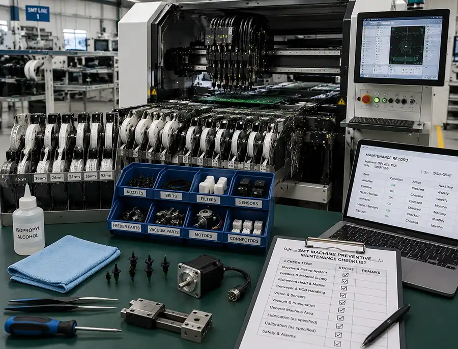
SMT Machine Preventive Maintenance Checklist
| Inspection Area | Typical Conditions to Check | Record or Follow-Up |
|---|---|---|
| Nozzles and pickup system | Contamination, blockage, tip damage, installation and pickup consistency | Record repeated pickup changes and confirm the nozzle type if replacement is required |
| Feeders and material supply | Loading, tape path, component presentation, seating, interface cleanliness and visible wear | Record recurring presentation errors together with the feeder family and material condition |
| Placement head and motion system | Movement, noise, vibration, cables, hoses, connectors and repeated position-related symptoms | Compare changes over time and follow approved service procedures when investigation is required |
| Conveyor and PCB handling | Rails, belts, stops, clamps, supports, width adjustment, sensors and transfer condition | Document repeated transfer delays, obstructions or board-handling interruptions |
| Vision and sensors | Camera, lighting and sensor cleanliness, cables, connectors and recurring feedback irregularities | Clean approved external areas and record repeated measurement or feedback changes |
| Vacuum and pneumatic systems | Leakage symptoms, filters, tubing, valves and connection condition | Record instability and confirm the affected component before replacement |
| General machine area | Loose components, tape waste, damaged cables, unusual sound and production-area cleanliness | Remove approved debris and document conditions requiring further review |
The checklist provides general inspection categories rather than a universal daily, weekly or monthly schedule. Frequency should reflect the machine documentation, production usage, environment and maintenance history.
Inspect Nozzles and Pickup-Related Conditions
Nozzles directly contact and hold components during pickup and placement, so visible contamination, blockage, tip damage, deformation or installation problems may affect pickup consistency.
Changes worth recording may include increasing pickup failures, component drops or inconsistent pickup under the same product setup. These observations should be reviewed together with component presentation, carrier-tape condition, vacuum supply, pickup position, machine setup and vision measurements.
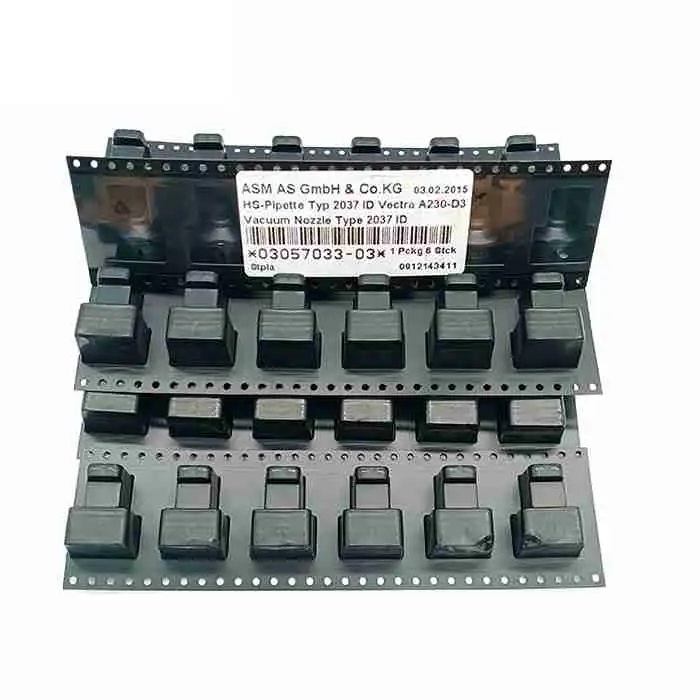
If inspection confirms damaged or unsuitable pickup tooling, review available SMT nozzles and verify the nozzle code, head interface and machine configuration before replacement.
Inspect Feeders and Component-Supply Conditions
Feeder inspection should consider both the equipment and the material being presented for pickup.
Check correct loading, tape path, cover-tape condition, component presentation, feeder seating, interface cleanliness, visible wear and damaged guides or moving parts.
When repeated presentation errors occur, record the feeder family, material condition, pickup position and machine configuration. This information helps distinguish feeder wear from packaging, setup, nozzle, sensor or communication conditions.
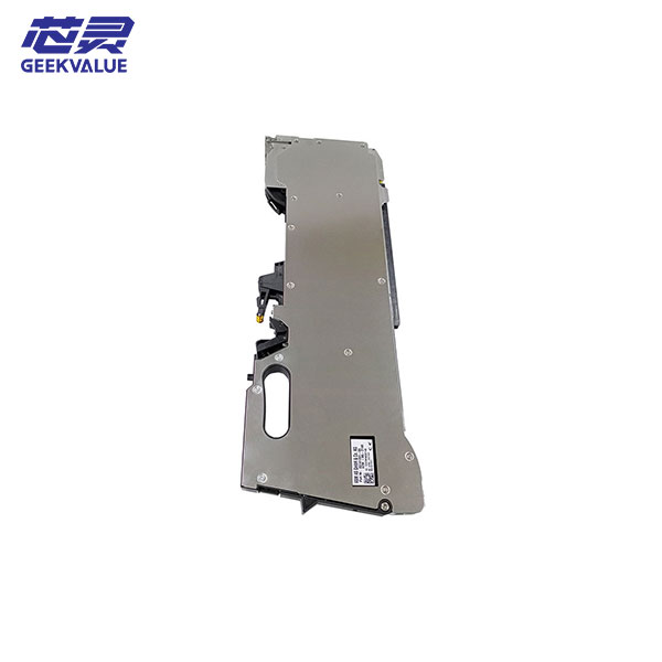
If equipment wear is confirmed, review suitable SMT feeders or feeder-related parts using the exact feeder family, platform and interface information.
Monitor Placement Heads and Motion Systems
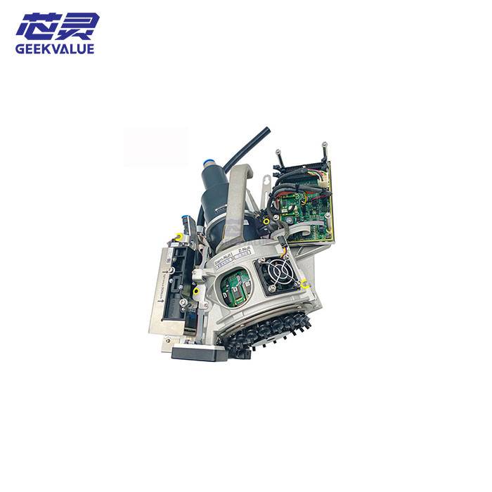
Placement heads carry the pickup tools, vision systems measure position and orientation, control systems calculate and coordinate commands, and motors and drives execute movement.
Maintenance teams may monitor abnormal movement, unusual sound, increasing vibration, repeated position-related symptoms, cable or hose wear, connector condition and changes in placement-head operation.
Record recurring changes and compare them with previous production. Adjustment, disassembly and electrical service should follow approved procedures for the exact machine.
Inspect Conveyor and PCB-Handling Conditions
Conveyor and board-handling components transport and support the PCB during production. Typical inspection areas include rails, belts, stops, clamps, board supports, width-adjustment mechanisms, sensors, transfer paths and interfaces with connected equipment.
Repeated transfer delays, inconsistent stopping, visible belt wear or recurring sensor interruptions should be documented. Conveyor components manage physical board movement, while sensors, vision and control systems support coordinated board handling.
Check Vision, Sensors, Vacuum and Supporting Systems
Supporting systems provide measurement, feedback, component holding and machine-status information.
Typical checks may include camera and lighting cleanliness, sensor contamination, cable damage, loose connectors, vacuum-leakage symptoms, filter condition, tubing damage and valve irregularity.
Routine inspection should remain limited to approved maintenance activities. Electrical work, parameter changes and internal service should follow the documentation and authorization required for the exact machine.
Monitor Changes Before a Complete Failure
Preventive maintenance should not only ask whether the machine is currently operating. It should also determine whether its condition is changing compared with previous production.
Developing trends may include:
Increasing pickup failures
More frequent feeder-related stops
Repeated alarms at the same machine position
Growing vacuum instability
Increasing recognition rejection
Noise or vibration becoming more frequent
Slower PCB transfer
Recurring cable or connector problems
More frequent operator intervention
Declining output under the same product setup
Repeated, persistent or gradually worsening changes provide stronger evidence than an isolated event. Comparing current observations with earlier records helps maintenance teams decide when further investigation or spare-parts preparation is justified.
Keep Maintenance Records That Support Decisions
Maintenance records turn individual observations into historical evidence.
Useful record fields may include:
Date
Machine model and machine position within the production line
Product being assembled
Observed condition or symptom
Inspection performed
Cleaning or adjustment completed
Part inspected
Part number when known
Replacement performed
Follow-up result
Repeated occurrence
Technician notes
These records can reveal recurring conditions, developing wear, frequently replaced parts and long-lead items that may justify local stock. They provide evidence for maintenance and inventory decisions rather than automatically identifying a root cause.
Plan Critical SMT Spare Parts Before They Are Needed
Preventive maintenance should identify which unavailable components could cause an extended production interruption.
A part may deserve spare-inventory consideration when it is:
Critical to production
Used across several machines
Associated with recurring wear or replacement history
Difficult to obtain quickly
Required for production recovery
Without a practical temporary substitute
Possible examples include frequently used verified nozzles, selected feeder-related parts, sensors, belts, filters, vacuum components, cables, connectors and machine-specific motion components with long supplier lead times.
This is not a universal stock list. Each factory should base its plan on its machines, production requirements, maintenance history and supply risk before reviewing available ASM/SIPLACE SMT machine parts.
Decide Which Spare Parts and Quantities Are Practical
Spare-parts priority should reflect production risk rather than the number of products available in a catalogue.
Evaluate:
Number of machines using the part
Production criticality
Historical failure or consumption rate
Developing wear pattern
Supplier lead time
Availability of local support
Cost of production downtime
Availability of a temporary workaround
Storage requirements
Shelf life when applicable
Part cost
Ease of replacement
Confidence in exact part identification
Production Impact + Failure History + Lead Time + Machine Coverage + Replacement Difficulty + Identification Confidence = Spare-Parts Priority
Keeping more than one verified spare may be practical for parts used frequently across several important machines or consumed regularly, especially when supplier lead time is long. Quantity should be based on usage records and production exposure rather than a general recommendation to buy extra stock.
Verify and Organize Every Spare Before Stocking
A backup part is useful only when it matches the installed equipment. An incorrectly identified item can create false confidence and may not support production recovery when required.
Before adding a spare to inventory, confirm:
Machine model and generation
Complete part number
Suffix or revision
Connector arrangement
Mounting arrangement
Electrical rating when applicable
Installed configuration
Required quantity
Use a structured process to identify the correct SMT machine part before ordering. Exact labels, documentation and installed-machine information should take priority over visual similarity.
After verification:
Label the part with its complete number and suffix
Record the supported machine or configuration
Store related documentation or photos
Record quantity and storage location
Protect connectors and sensitive surfaces
Separate verified parts from unidentified items
Track usage and review stock after a replacement is used
Storage requirements for sensitive items should follow the applicable manufacturer documentation.
When to Request SMT Part Confirmation
Request additional confirmation when a part number is incomplete, the suffix is unclear, several versions look similar, the machine has been modified, the installed part may not be original or connector and mounting details differ.
Prepare the machine model and generation, complete part number and suffix, clear part and label photos, installed location, connector and mounting details, relevant maintenance history and required quantity.
Send this information through WhatsApp when the exact replacement cannot be confirmed from internal documentation. Complete evidence supports a more efficient review of the likely replacement direction.
Request Support for Verified SMT Spare-Parts Planning
Use maintenance records, production criticality and supplier lead time to identify which verified replacement parts should be prepared in advance.
Contact us through WhatsApp when you need help confirming an ASM/SIPLACE part or reviewing practical spare-part requirements for your installed machines.
Frequently Asked Questions About SMT Machine Maintenance
What should be included in SMT machine preventive maintenance?
Preventive maintenance may include cleaning, visual inspection, operational checking, condition monitoring, maintenance records, investigation of developing changes and planning for selected verified spare parts.
How often should an SMT machine be maintained?
Maintenance frequency should follow the machine manual and consider production usage, operating environment, factory procedures, installed configuration and maintenance history. One interval is not suitable for every machine.
Does every SMT machine alarm mean a part must be replaced?
An alarm is a starting point for investigation. Material condition, setup, contamination, sensor feedback, communication, wear and other machine conditions should be reviewed before replacement is selected.
Why is maintenance history important for spare-parts planning?
Maintenance history shows which conditions recur, which parts are replaced frequently and which long-lead items could delay production recovery.
Which SMT spare parts should a factory keep in stock?
Stock should be based on production criticality, machine coverage, maintenance history, usage rate, supplier lead time, downtime impact and confidence in exact part identification.
Why should spare parts be verified before stocking?
A spare with the wrong revision, connector, mounting arrangement or machine compatibility may not be usable when production recovery depends on it.
Conclusion: A documented SMT machine maintenance process helps factories detect developing changes, make better service decisions and prepare verified critical replacements before they are urgently required. Combining routine inspection, condition monitoring, maintenance history and practical spare-parts planning supports more efficient production recovery when maintenance intervention becomes necessary.