The SIPLACE D2i is a dual-gantry SMT placement machine developed for production that combines small-component speed with the flexibility to handle standard SMDs and larger IC packages. Its two gantries can be configured with 12-nozzle or 6-nozzle Collect
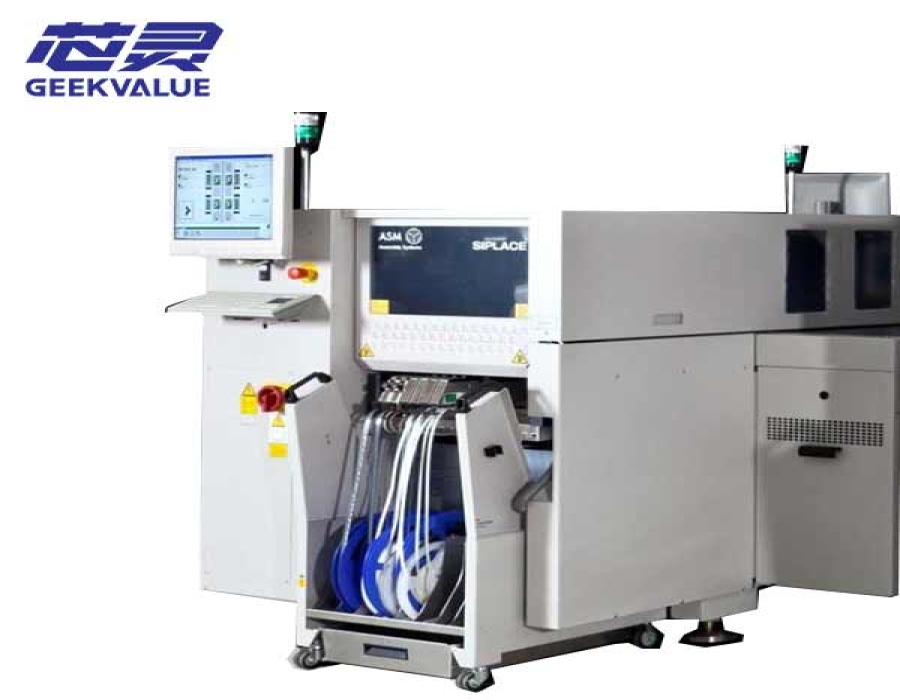
The SIPLACE D2i is a dual-gantry SMT placement machine developed for production that combines small-component speed with the flexibility to handle standard SMDs and larger IC packages. Its two gantries can be configured with 12-nozzle or 6-nozzle Collect & Place heads, allowing the machine to be adapted to different component mixes.
Placement output and component capability depend on the installed head combination, cameras, nozzles, conveyor and optional packages. Available machines may also differ in software version, feeder equipment and included accessories. These details are confirmed before quotation.
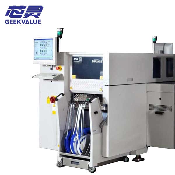
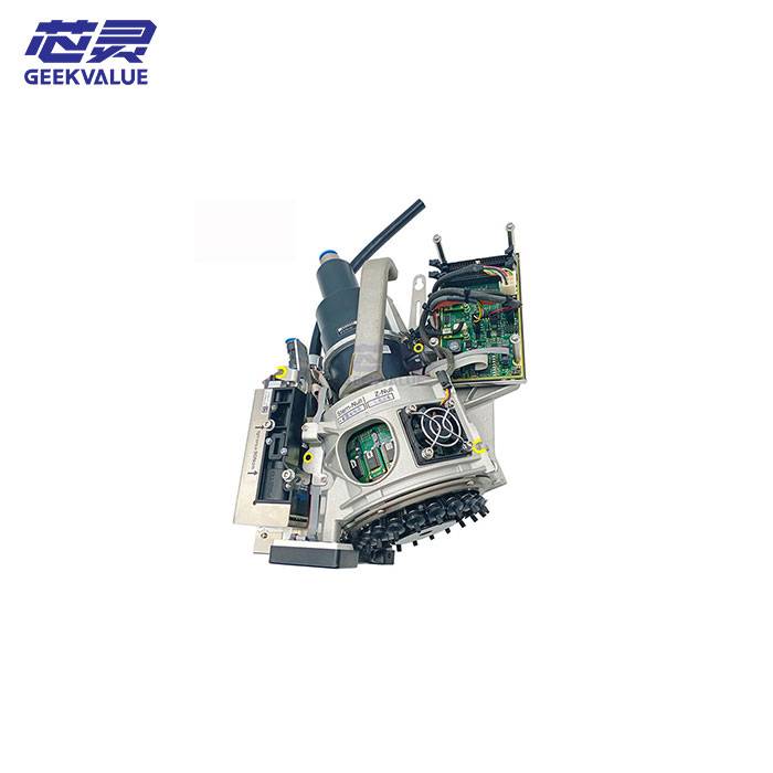
Each SIPLACE D2i gantry carries one Collect & Place head. During a placement cycle, the head collects several components from the stationary feeder area, centers and rotates them while moving toward the PCB, and then places them at the programmed positions.
The D2i does not use a TwinHead or a separate large-component Pick & Place head in the documented configuration. Its production range is defined by three possible combinations of C&P12 and C&P6 heads.
| Machine Structure | Two placement gantries |
|---|---|
| Placement Head Options | 12-nozzle Collect & Place and 6-nozzle Collect & Place |
| Maximum IPC 9850 Rating | 27,200 components per hour |
| Maximum SIPLACE Benchmark | 31,000 components per hour |
| Theoretical Maximum | 40,500 components per hour |
| Overall Documented Component Range | 01005 to 27 × 27 mm, depending on head, camera and optional equipment |
| Reference Feeder Capacity | Up to 90 tracks with 3 × 8 mm S feeder modules |
A machine equipped with two C&P12 heads provides the highest reference output. A mixed C&P12 and C&P6 configuration sacrifices some chip-placement speed but expands the practical range of IC packages. Two C&P6 heads place greater emphasis on component flexibility.
| Head Combination | IPC 9850 | SIPLACE Benchmark | Theoretical Maximum | Production Focus |
|---|---|---|---|---|
| 2 × C&P12 | 27,200 cph | 31,000 cph | 40,500 cph | Highest reference output for small and standard components |
| C&P12 + C&P6 | 20,900 cph | 23,000 cph | 32,000 cph | Balanced speed and component flexibility |
| 2 × C&P6 | 16,500 cph | 19,500 cph | 23,000 cph | Mixed production with a greater proportion of larger IC packages |
These figures represent different test or calculation conditions. The theoretical value is not the expected output of a normal production program. Actual throughput depends on the PCB layout, component mix, feeder positions, rotations, transport time, program optimization and equipment condition.
| Head Configuration | Reference Component Range | Maximum Height | Maximum Weight | Reference X/Y Accuracy |
|---|---|---|---|---|
| C&P12 with Camera Type 28 | 0402 to 18.7 × 18.7 mm | 6 mm | 2 g | ±50 µm at 3σ |
| C&P12 with Camera Type 30 | 01005 with the required package, up to 18.7 × 18.7 mm | 6 mm | 2 g | ±50 µm at 3σ |
| C&P6 with Camera Type 30 | 0201 to 27 × 27 mm | 8.5 mm | 5 g | ±52.5 µm at 3σ |
| Programmable Placement Force | 2.4 N to 5.0 N |
|---|---|
| C&P12 Angular Accuracy | ±0.53° at 3σ |
| C&P6 Angular Accuracy | ±0.225° at 3σ |
| Supported Package Examples | Standard chips, SO packages, DRAM, TSOP, QFP, PLCC, BGA, µBGA and compatible flip-chip or bare-die packages |
Package geometry, component tolerances, camera type and nozzle selection can reduce the usable range. The documented 27 × 27 mm limit applies to the C&P6 configuration and should not be attributed to a machine fitted only with C&P12 heads.
The SIPLACE D2i platform was prepared for 01005 placement, but the function is not available from the model name alone. The original specification requires a C&P12 head with a high-resolution Type 30 camera and the optional 01005 package.
The package includes dedicated Type 905 nozzles and components for low-force placement. Compatible 01005 S feeder modules and suitable software are also required. The 2012 specification lists station software 605.03 SP2 and SIPLACE Pro 10 or later for this configuration.
Before selecting a used D2i for 01005 production, the camera, nozzles, feeder modules, software version and installed option status should be checked together.
The D2i was available with a single conveyor or a flexible dual conveyor. In dual-conveyor mode, two PCBs can be processed synchronously as a combined panel or asynchronously, allowing one board to enter the placement area while the other track is being processed.
| Conveyor Arrangement | Standard PCB Range | Maximum with Required Options |
|---|---|---|
| Single Conveyor | 50 × 50 mm to 460 × 460 mm | Up to 610 × 508 mm with long-board and wide-board equipment |
| Flexible Dual Conveyor | 50 × 50 mm to 460 × 216 mm | Up to 610 × 242 mm with the applicable options |
| Dual Conveyor in Single-Conveyor Mode | 50 × 50 mm to 460 × 380 mm | Up to 610 × 430 mm with the applicable options |
| PCB Thickness | 0.3 to 4.5 mm as standard |
|---|---|
| Maximum PCB Weight | 3 kg |
| Component-Free Handling Edge | 3 mm |
| Reference PCB Changeover Time | Less than 2.5 seconds |
| Production-Line Interface | SMEMA or Siemens interface, depending on configuration |
| Flexible Dual-Conveyor Modes | Synchronous or asynchronous operation |
Maximum board formats require the corresponding conveyor options. The installed track type, fixed rail position, transport direction, conveyor height and interface should be confirmed before integrating the machine into an existing SMT line.
The D2i uses two movable component changeover tables. Each table provides up to 15 feeder-module locations and can be prepared outside the machine while production continues.
| Component Changeover Tables | Two |
|---|---|
| Feeder Locations per Table | Up to 15 locations |
| Maximum Reference Capacity | 90 tracks using 3 × 8 mm S feeder modules |
| Reference Table Changeover Time | Less than one minute |
| Supported Feeding Methods | Tape feeders, bulk cases, stick magazines, DIP modules and compatible application-specific feeder modules |
| Optional Setup Verification | Barcode reader and Setup Center functions |
The 90-track figure describes maximum platform capacity. It does not mean that the machine is supplied with 90 feeders. Changeover tables, feeder modules, nozzles and special feeding equipment should be listed separately in the quotation.
The SIPLACE D2i uses digital cameras to recognize component shape, color and position before placement. The system measures the component on the nozzle and corrects pickup offsets before the part is placed.
Vacuum sensors check whether a component has been picked up and released correctly. Force sensors monitor the programmed placement force and compensate for differences in pickup height or uneven PCB surfaces. PCB warpage checking and individual component image records provide additional process information.
Camera type and optional sensors vary by head configuration. The high-resolution camera required for the smallest components should be verified on the available machine.
| Basic Machine Length | 1,572 mm |
|---|---|
| Width with Changeover Tables | Approximately 2,285 mm |
| Basic Machine Weight | Approximately 2,192 kg |
| Weight with Two Changeover Tables | Approximately 2,364 kg |
| Fully Configured Reference Weight | Approximately 2,436 kg |
| Nominal Apparent Power | 2 to 3 kVA |
| Operating Air Pressure | Approximately 5.2 bar |
Supply voltage, machine height and air consumption differ according to regional electrical version, conveyor height and installed options. Facility requirements should be confirmed from the identification and configuration of the machine offered.
The SIPLACE D2i is best suited to production dominated by chips, standard SMDs and medium-size IC packages. A dual C&P12 configuration favors placement output, while a mixed C&P12 and C&P6 arrangement provides a broader package range without moving to a large-component placement platform.
For boards containing heavy connectors, tall components or packages larger than 27 × 27 mm, another machine with a suitable Pick & Place or odd-shaped-component head may be required.
| Item | Why It Must Be Checked |
|---|---|
| Placement Head Combination | Determines the reference output and the component range available on the machine. |
| Component Camera Type | Camera Type 30 is required for the documented smallest-component configurations. |
| 01005 Package | 01005 production requires dedicated nozzles, feeders, software and supporting equipment. |
| Conveyor Configuration | Defines PCB dimensions, track operation and compatibility with adjacent equipment. |
| Wide-Board and Long-Board Options | The maximum PCB formats are only available when the applicable options are installed. |
| Feeders and Changeover Tables | They may be included with the machine or supplied separately. |
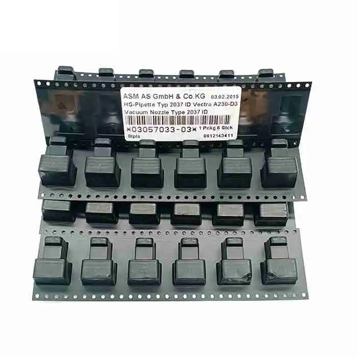
| Nozzles and Nozzle Changers | The installed tooling must match the intended component packages. |
| Software Version | Software compatibility affects 01005 capability, programming and line integration. |
GEEKVALUE can assist with sourcing SIPLACE D2i placement machines according to current availability. Machines carrying the same model name may have different placement heads, cameras, conveyor systems, feeders, software versions and accessory packages.
Send us your PCB dimensions, smallest and largest components, required output, feeder requirements and destination country. We will confirm the available machine configuration, current photos, condition, included accessories, price and estimated delivery time before quotation.
No. The 40,500 cph figure is the theoretical maximum for a machine fitted with two C&P12 heads. The corresponding SIPLACE benchmark is 31,000 cph and the IPC 9850 rating is 27,200 cph.
No. The platform is prepared for 01005 placement, but the available machine requires C&P12 heads with the appropriate high-resolution camera, dedicated 01005 package, suitable feeders, nozzles and compatible software.
The reviewed original specification lists 27 × 27 mm as the maximum documented component size for the C&P6 head. Larger or heavier components normally require a different placement-head platform.
No. The number describes the maximum track capacity when both changeover tables use 3 × 8 mm S feeder modules. The actual feeder quantity and included accessories must be confirmed in the quotation.
If you are not sure whether this product matches your machine, send us the model, label photo or old part picture for checking.