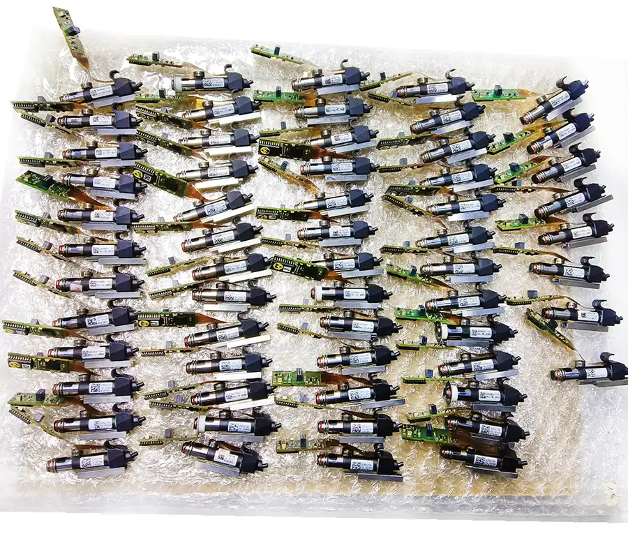
The Siemens SIPLACE HF3, written as SIPLACE HF/3 in original Siemens documentation, is the three-gantry version of the SIPLACE HF placement platform. It was developed for SMT production that needs to handle standard SMDs, integrated circuits and larger or
The Siemens SIPLACE HF3, written as SIPLACE HF/3 in original Siemens documentation, is the three-gantry version of the SIPLACE HF placement platform. It was developed for SMT production that needs to handle standard SMDs, integrated circuits and larger or more demanding packages within one machine concept.
An HF3 cannot be evaluated by the model name alone. Its placement capability depends on the installed heads, vision modules, conveyor arrangement, feeder setup, software version and optional equipment. GEEKVALUE confirms the configuration, machine condition, included accessories and delivery details of the available unit before quotation.
The SIPLACE HF platform combines two placement methods. Collect & Place heads pick up several components during each cycle and are used for standard SMD and IC placement. TwinHead works on the Pick & Place principle and is intended for larger, fine-pitch or more complex components.
On the HF3, the head combination installed across the three gantries determines the balance between placement output and component flexibility. A machine configured mainly with Collect & Place heads will have different production characteristics from one equipped with a TwinHead for large or special components.
The following information is based on the original SIPLACE HF platform specification. It describes the reference capabilities of the available head technologies and should not be treated as the confirmed configuration of every HF3 machine.
| Placement Head | Placement Method | Reference Component Range | Reference Component Height | Typical Role |
|---|---|---|---|---|
| 12-Segment Collect & Place Head | Collect & Place | 0201 to 18.7 × 18.7 mm with the standard vision module | Up to 6 mm | Standard SMD and high-speed component placement |
| 6-Segment Collect & Place Head | Collect & Place | 0603 to 32 × 32 mm with the standard vision module | Up to 8.5 mm | ICs and components larger than the normal chip range |
| TwinHead | Pick & Place | Up to 85 × 85 mm or 125 × 10 mm; up to 200 × 125 mm with restrictions | Up to 25 mm, with larger heights subject to confirmation | Large, fine-pitch, special and more demanding components |
Vision modules, nozzles and head options affect the applicable component range. The actual head type and installed vision system should therefore be checked against the available machine.
The SIPLACE HF platform was available with single- and dual-conveyor arrangements. The dual conveyor supports synchronous or asynchronous board transport and can also operate in a single-conveyor mode. The applicable PCB format depends on the installed conveyor and whether the long-board option is present.
| Conveyor Arrangement | Reference PCB Format | Configuration Note |
|---|---|---|
| Single Conveyor | 50 × 50 mm to 450 × 508 mm | Standard HF platform configuration |
| Single Conveyor with Long-Board Option | 50 × 80 mm to 610 × 508 mm | Requires the optional long-board setup |
| Dual Conveyor | 50 × 50 mm to 450 × 250 mm per reference format | Supports synchronous or asynchronous transport |
| Dual Conveyor with Long-Board Option | 50 × 80 mm to 610 × 250 mm | Requires the optional long-board setup |
| Dual Conveyor in Single-Conveyor Mode | 50 × 50 mm to 450 × 450 mm | Uses the dual conveyor as one wider transport path |
| Single-Conveyor Mode with Long-Board Option | 50 × 80 mm to 610 × 450 mm | Depends on both conveyor mode and optional equipment |
HF3 machines were supplied in different configurations. Two machines carrying the same model name may not have the same placement heads, conveyor, feeder capacity or supporting accessories. These points should be confirmed before comparing quotations.
| Item to Confirm | Why It Matters |
|---|---|
| Placement Head Combination | Determines component capability and has a direct effect on production output. |
| Vision Module and Nozzle Setup | Affects component recognition, applicable package range and placement accuracy. |
| Single- or Dual-Conveyor Configuration | Determines PCB width, lane arrangement and line integration requirements. |
| Feeders and Changeover Tables | Feeders may be included, optional or quoted separately from the main machine. |
| Tray Handling Equipment | A matrix tray changer or manual tray arrangement is not standard on every machine. |
| Software Version and Transport Direction | Should be checked for compatibility with the buyer’s existing SMT line and production setup. |
| Machine Condition and Available Documentation | Current photos, configuration details and equipment condition should match the quotation. |
GEEKVALUE supplies SIPLACE HF3 SMT placement machines according to current availability. Before issuing a quotation, we confirm the machine identification, installed heads, conveyor type, included accessories, available photos, equipment condition, price and estimated delivery time.
For a more accurate equipment match, provide your PCB dimensions, component range, preferred conveyor setup, feeder or tray requirements and destination country. When the required head configuration is not known, you can send the production information already available and contact us for further checking.
No. Placement output changes with the head combination, component mix, PCB program, feeder arrangement and condition of the machine. A single CPH figure should not be treated as the guaranteed production rate of every HF3. The available configuration must be confirmed before purchase.
No. HF-family machines could be configured with 12-segment Collect & Place heads, 6-segment Collect & Place heads and TwinHead technology. The installed combination needs to be checked on the machine being quoted.
Not necessarily. Feeders, nozzles, component changeover tables and matrix tray changers may be included or supplied separately. The quotation should list the accessories that form part of the offer.
Current photos, available configuration information and equipment condition can be confirmed during the inquiry and quotation process. Images used for general model identification should not be treated as proof of a specific machine configuration.
Send the destination country and any known requirements for PCB size, component range, head configuration, conveyor type, feeders and supporting accessories. When these details are not yet available, contact us with the intended production application for further discussion.
If you are not sure whether this product matches your machine, send us the model, label photo or old part picture for checking.