

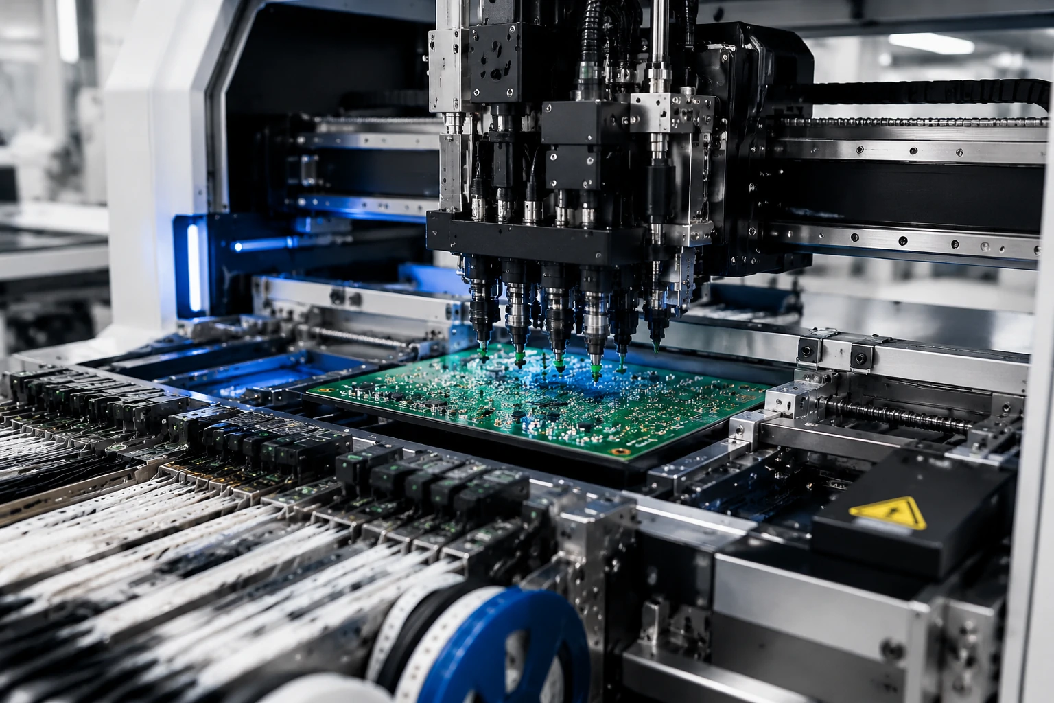
In this article, an SMT machine refers specifically to an automated pick-and-place machine used during the component-placement stage of printed circuit board (PCB) assembly. It follows prepared production data, establishes the actual PCB position, picks components from controlled supply positions, measures their position and orientation, corrects placement coordinates, and releases them at programmed PCB locations.
The operating process can be summarized as:
Production Data → PCB Positioning → Component Presentation → Pickup → Vision Measurement → Coordinate Correction → Placement → Repeat
This high-level process is common across SMT placement equipment, although exact head designs, camera arrangements, pickup methods and control sequences vary by machine platform and configuration.
1. Production Data Prepares the Placement Process
Before physical placement begins, the machine receives production information that defines which components are required and where each component should be placed on the PCB.
This information may include:
-
PCB or product program
-
Component identities and package information
-
Programmed PCB coordinates
-
Supply assignments
-
Nozzle or pickup-tool assignments
-
PCB fiducial information
-
Planned placement sequence
The machine does not independently decide component locations. The production program defines the intended placement, while positioning, measurement and control systems relate that information to the actual PCB and component conditions inside the equipment.
2. The PCB Enters and Establishes Its Position
The placement process begins when the PCB enters the machine through a conveyor or another supported board-handling system.
Depending on the machine design, rails, stops, clamps or board-support mechanisms may hold the PCB in a stable position during component placement. The machine then determines the relationship between the actual PCB position and the coordinates stored in the production program.
How PCB Fiducials Support Positioning
PCB fiducials are recognizable reference marks that commonly help the vision system determine board position, orientation and offset.
The machine may measure these reference points and compare their actual locations with the expected program data. This allows the control system to account for differences in:
-
X-axis position
-
Y-axis position
-
Board rotation
3. The Supply System Presents the Component
During the placement process, the component-supply system presents the required component at a controlled pickup position. For tape-packaged components, an SMT feeder commonly advances and presents the component for pickup.
Components may be supplied through:
-
Tape feeders
-
Trays
-
Tubes or sticks
-
Other supported supply systems
The supply system makes the required component available for pickup. It does not place the component onto the PCB.
For example, a tape feeder advances the carrier tape until the required component reaches the pickup area, while a tray system presents components at known tray positions. Other supply formats use different presentation methods depending on component packaging and machine configuration.
4. The Nozzle Picks Up the Component
Once the component is available at the pickup position, the placement head moves toward the supply area.
A suitable nozzle or pickup tool contacts the component and holds it for movement. Vacuum is commonly used for many surface-mount components, although pickup methods vary depending on component type and equipment design.
The nozzle and placement head perform different functions:
-
Nozzle: Contacts, holds and releases the component.
-
Placement head: Carries and moves the nozzle or pickup tool between operating stages.
The nozzle directly interacts with the component, while the placement head provides the controlled movement required for pickup, measurement and placement.
Depending on the machine platform, pickup confirmation may involve sensor feedback, vacuum information, vision data or other supported methods.
5. Vision Measurement and Placement Correction
After pickup, the component may not be perfectly centered or correctly oriented on the nozzle. Before placement, the vision system may measure its actual position and orientation.
Component Vision Measurement
The placement vision system may evaluate:
-
Component presence
-
Component position relative to the nozzle
-
Rotational orientation
-
Recognizable edges, shapes or features
-
Whether the pickup condition is acceptable
This measurement stage provides information about the actual pickup condition of the component before placement.
Offset and Rotation Correction
The control system may combine:
-
Programmed component coordinates
-
PCB-position measurements
-
Component-position measurements
-
Rotation information
Using this information, the control system may calculate corrections for:
-
X-axis position
-
Y-axis position
-
Component rotation
-
Final placement coordinates
For example, if a component is slightly rotated after pickup, the control system can calculate the required correction before the motion system moves it to the target location.
The exact camera arrangement, correction method and software calculation vary by machine platform and should not be considered identical across all SMT placement systems.
Placement Vision vs AOI
Placement vision and automated optical inspection serve different purposes.
-
Placement vision: Measures component position and orientation before placement so the machine can execute the placement operation.
-
AOI: Inspects the assembled PCB after placement or reflow, depending on where the inspection system is positioned in the production process.
Placement vision supports positioning before the component reaches the PCB, while AOI evaluates PCB assembly results. They are not the same system or function.
6. The Placement Head Moves and Places the Component
After the required position and rotation corrections are calculated, the motion system directs the placement head to carry the component toward its programmed PCB location.
The placement operation may include:
-
Movement toward the corrected target coordinate
-
Component rotation when required
-
Controlled lowering toward the programmed placement height
-
Release at the intended PCB position
In a standard reflow process, the component is commonly placed onto solder-paste deposits previously printed on the PCB. The tackiness of the solder paste helps hold the component temporarily in position, but the placement machine does not create the permanent solder joint.
Permanent electrical and mechanical connections are normally formed later during reflow soldering.
7. The Placement Cycle Repeats
The machine repeats the functional cycle for the components required by the production program:
Present → Pick → Measure → Correct → Move → Place → Repeat
Depending on the machine configuration, production may involve multiple nozzles, multiple placement heads, parallel pickup or placement operations, or multiple board lanes or work positions.
These configurations may change how operations overlap, but the same functional relationship remains: components are presented, picked, measured, corrected and placed according to prepared production information.
What Happens When Pickup or Recognition Is Unsuccessful?
If the machine cannot confirm a pickup or obtain an acceptable recognition result, its response depends on the machine platform, program settings and error condition.
The machine may:
-
Retry the operation
-
Reject the component
-
Record an error or production event
-
Stop the process
-
Request operator attention
Detailed causes, alarm interpretation and corrective procedures depend on the specific machine and belong to equipment-specific troubleshooting resources.
What Happens After Component Placement?
After the required components have been placed, the PCB leaves the placement machine and moves to the next manufacturing stage.
The typical sequence is:
Placed PCB → Reflow Soldering → Inspection
During reflow, the solder paste is heated so that it forms permanent solder joints between component terminations and PCB pads. Inspection equipment may then evaluate placement, soldering and other assembly conditions according to the production process.
Component placement and permanent soldering are therefore separate functions. The pick-and-place machine positions components, while the reflow process forms the solder joints.
How ASM/SIPLACE Machines Apply This Placement Process
ASM/SIPLACE SMT placement machines apply the same general sequence of programmed component supply, pickup, measurement, correction and PCB placement.
Available machine generations and configurations may differ in placement-head setup, supported supply systems, board handling and software functions. When evaluating a machine, confirm the required PCB dimensions, component and package range, production volume and existing line configuration against the actual equipment specification.
Explore available ASM/SIPLACE placement machines, or provide your PCB, component and production requirements when evaluating a specific configuration.
Frequently Asked Questions About How SMT Machines Work
How does an SMT pick-and-place machine work?
An SMT pick-and-place machine follows prepared production data, establishes the PCB position, receives components from a supply system, picks them with a nozzle, measures their position and orientation, corrects placement coordinates and releases them at programmed PCB locations.
How does the machine know where to place each component?
The machine uses production data containing component coordinates and related information. PCB-position measurements and component measurements help the control system calculate the corrected placement target.
What is the difference between a nozzle and a placement head?
The nozzle contacts, holds and releases the component. The placement head carries and moves the nozzle or pickup tool between the supply position, measurement stage and PCB placement location.
Does an SMT placement machine solder components?
No. The placement machine positions components on the PCB. Permanent solder joints are normally formed afterward during reflow soldering.
Conclusion: An SMT pick-and-place machine combines programmed production data, PCB positioning, controlled component supply, nozzle pickup, vision measurement, control-system correction and placement-head movement to place components at programmed PCB locations. After the placement cycle is complete, the board proceeds to reflow soldering and inspection.